Electric convection oven

a convection oven and electric technology, applied in the field of commercial electric ovens, can solve the problem of reducing the cooking space within the oven cavity,

Inactive Publication Date: 2005-08-23
BLODGETT HLDG
View PDF5 Cites 18 Cited by
  • Summary
  • Abstract
  • Description
  • Claims
  • Application Information

AI Technical Summary

Benefits of technology

[0009]It has been discovered that an electric convection oven can be provided wherein circulation is efficient and also wherein a separate lining, and space for the heat source is not necessary.

Problems solved by technology

In gas fired convection ovens it is necessary to house burners within the oven and this requirement diminishes the available cooking space within the oven cavity.

Method used


Image

  • Electric convection oven
  • Electric convection oven
  • Electric convection oven

Examples


Embodiment Construction

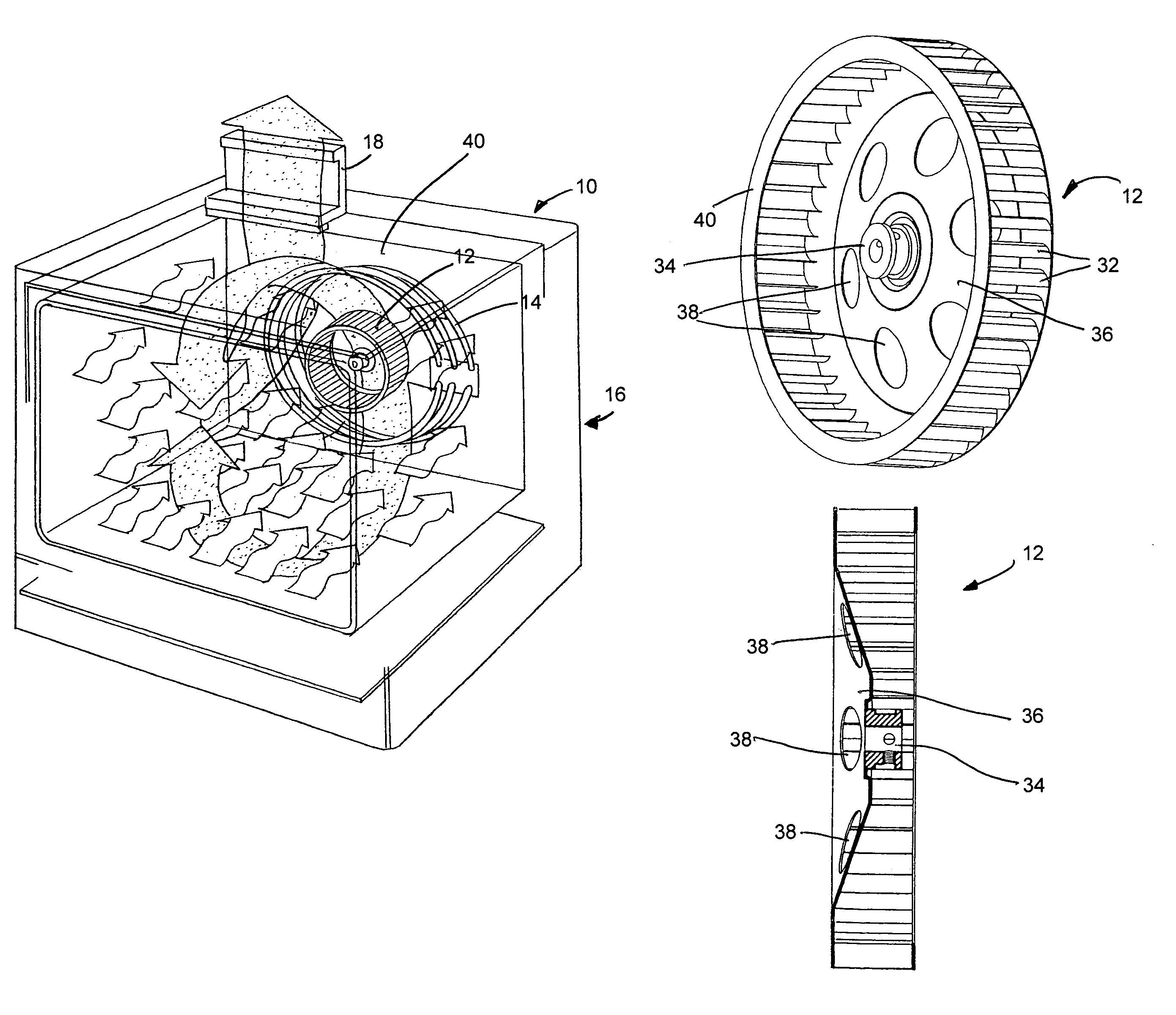
[0023]The oven of this invention 10 uses a squirrel cage fan 12 to circulate air from within the oven cavity through a bank of heating coils 14 wherein the air is heated and returned to the oven cavity 16. Air from within the cavity 16 is vented through a conventional flue 18.

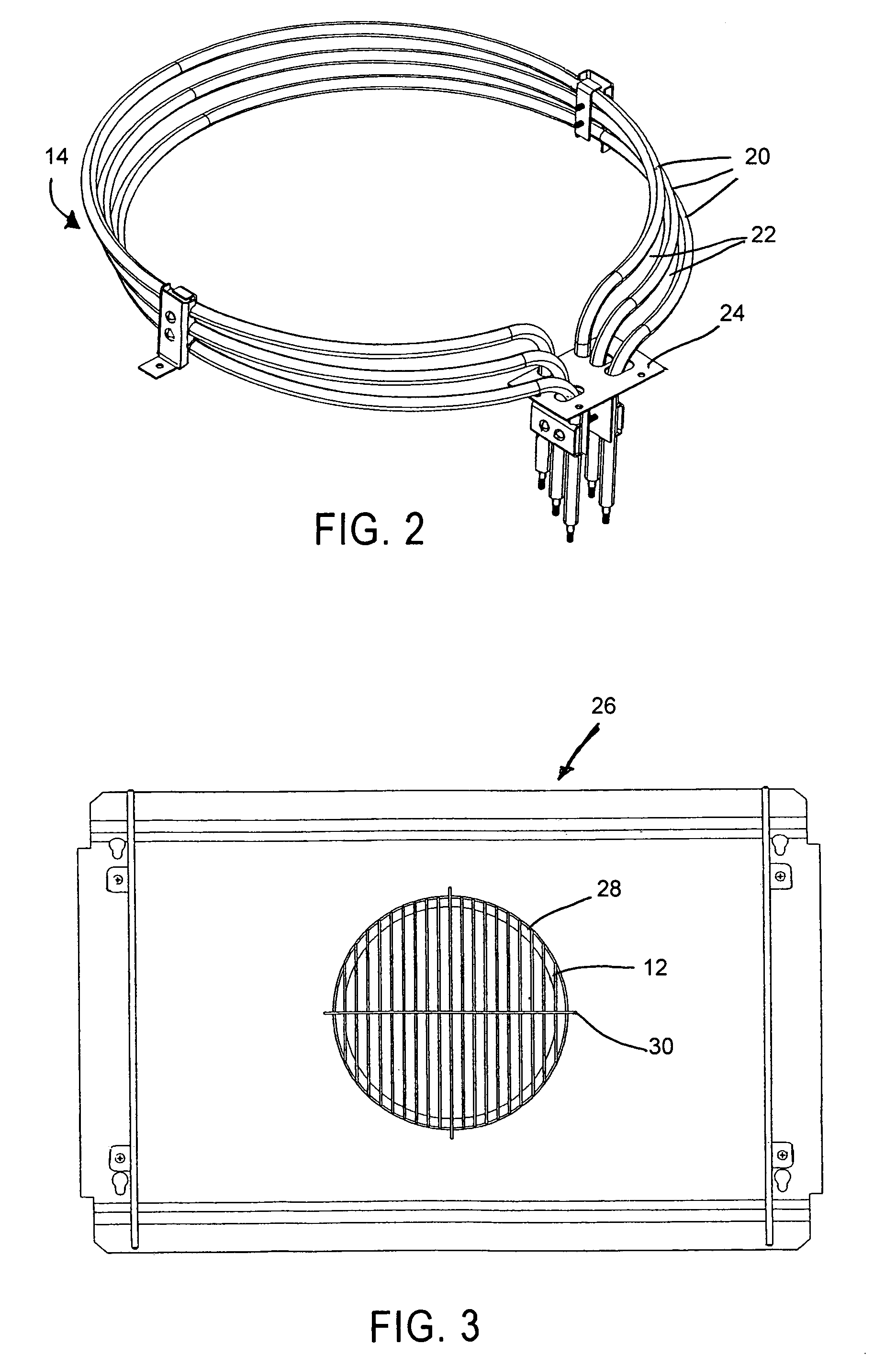
[0024]The heating means 14 is preferably a plurality of resistance elements 20 which are circular, and surround the fan 12. Spaces 22 are disposed between elements 20 to permit the passage of air from the fan therethrough. Heating elements 14 would be mounted by plate 24 and coupled to a source of electrical energy (not shown).

[0025]With attention to FIG. 3, a baffle plate 26 having a central opening 28 is disposed between the fan 12 and the cooking cavity 16. The fan 12 is shown schematically in FIG. 3. The central opening 28 preferably would have a mesh protector 30 to minimize food particles entering the fan itself.

[0026]Baffle plate 26 is dimensioned to permit the passage of heated air from the fan around t...


PUM


Abstract

An electric convection oven is provided wherein a squirrel cage fan is used to circulate air through a circular bank of heating coils surrounding the fan and into the oven. The coils wrap around the fan and are spaced from each other so that air from the fan will pass through the coils and into the oven. The fan is provided with a concave centrally located plate for drawing air from within the oven into the fan for recirculation through the heating coils and to return to the oven.

Description

BACKGROUND OF THE INVENTION[0001]This invention is related to a commercial electric oven and in particular to an electric convection oven which re-circulates heated air efficiently for uniform cooking.DESCRIPTION OF THE PRIOR ART[0002]Convection ovens operate by circulating heated air within an oven and the efficiency of this circulation dictates the quality of the cooking. It is necessary then to avoid hot spots and to uniformly disperse heated air within the oven cavity.[0003]In commercial kitchens, space is often at a premium. The overall outside dimensions of an oven are very important, then, as it is necessary to fit the kitchen equipment into the available space. Obviously, it would be desirable to maximize the cooking capacity of each oven within the given outside dimensions.[0004]In gas fired convection ovens it is necessary to house burners within the oven and this requirement diminishes the available cooking space within the oven cavity. In certain of such gas fired convec...

Claims


Application Information

Patent Timeline
Patent Type & Authority Patents(United States)
IPC IPC(8): A21B1/00A21B1/26F24C15/32
CPCF24C15/325
Inventor SMITH, ROBERT L.SHANGRAW, DAVID
Owner BLODGETT HLDG
Why Eureka
Try Eureka