System and method for placing endocardial leads

a technology of endocardial leads and leads, which is applied in the field of system and method for placing endocardial leads, can solve the problems of permanently implantable endocardial leads, difficult to locate the desired path, and difficulty in routing an endocardial lead along a desired path to implant the electrode or electrodes in a desired implantation site,

Inactive Publication Date: 2005-08-23
MEDTRONIC INC
View PDF34 Cites 57 Cited by
  • Summary
  • Abstract
  • Description
  • Claims
  • Application Information

AI Technical Summary

Benefits of technology

[0015]The current invention provides an improved system and method for deploying medical electrical leads. According to one embodiment, a guiding device such as a guidewire is used to navigate the vascular system of a body. The guiding device includes a fixation member that can be deployed to maintain the guiding device at a desired location within the vascular system. The fixation member may be an inflatable device such as a balloon. Alternatively, the fixation member may be an expandable device constructed of flexible fibers that has both an expanded and a contracted state.

Problems solved by technology

Routing an endocardial lead along a desired path to implant the electrode or electrodes in a desired implantation site, either in a chamber of the heart or in the selected cardiac vein or coronary artery, can be difficult.
Anomalies in the vascular anatomy and the number of branch veins associated with the anatomy make locating the desired path challenging.
One difficulty with systems that completely surround the cardiac lead is that permanently implantable endocardial leads are formed typically with a proximal connector end assembly having a diameter exceeding that of the lead body.
A smaller introducer that is designed to be split or slit may be used in the alternative, but these types of introducer are more difficult to manufacture.
Such a lead must be coupled to an adapter before it conforms to a standard, which is both inconvenient, and can result in a diminished reliability.
This results in a significant amount of friction that can make lead placement difficult.
Such retraction of the relatively bulky carriage presents the possibility of damage to an artery or vein by the carriage.
Because of unintended movement of the guidewire that typically occurs during the process of disengaging the electrode from the carriage, the distal end of the lead will not necessarily be positioned at the desired implant location.
This adds time and complexity to the implant procedure.
One problem with the systems described in the foregoing patents is that no anchoring mechanism is provided to maintain the guiding device such as the guidewire in a stationary position while the leads are being advanced to the desired implant site.
This can cause the guidewire to become dislodged.

Method used


Image

  • System and method for placing endocardial leads
  • System and method for placing endocardial leads
  • System and method for placing endocardial leads

Examples


Embodiment Construction

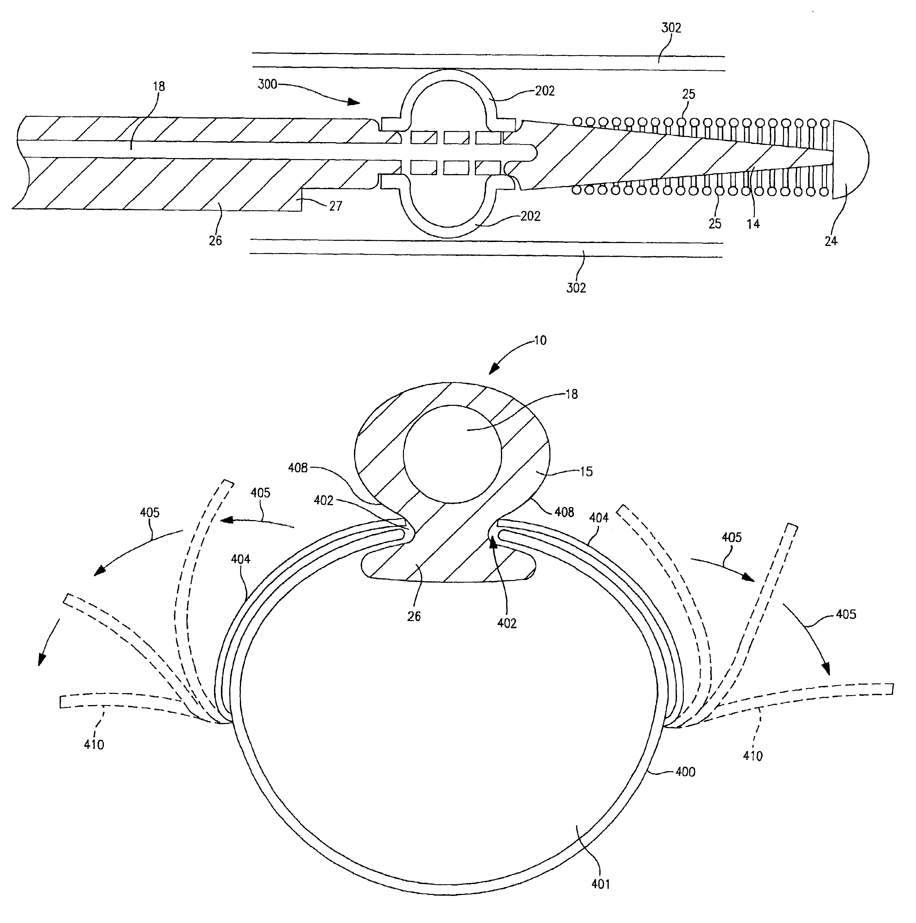
[0048]The current invention provides a system and method for introducing one or more electrodes into cardiac veins or coronary arteries. The system includes a low profile guiding device having a fixation mechanism at the distal tip for anchoring the guiding device in position while one or more electrodes are advanced over the body of the guiding device. In one embodiment, the fixation mechanism is capable of retracting such that it is co-axial with the guiding device for easy withdrawal of the device after electrode placement is complete.

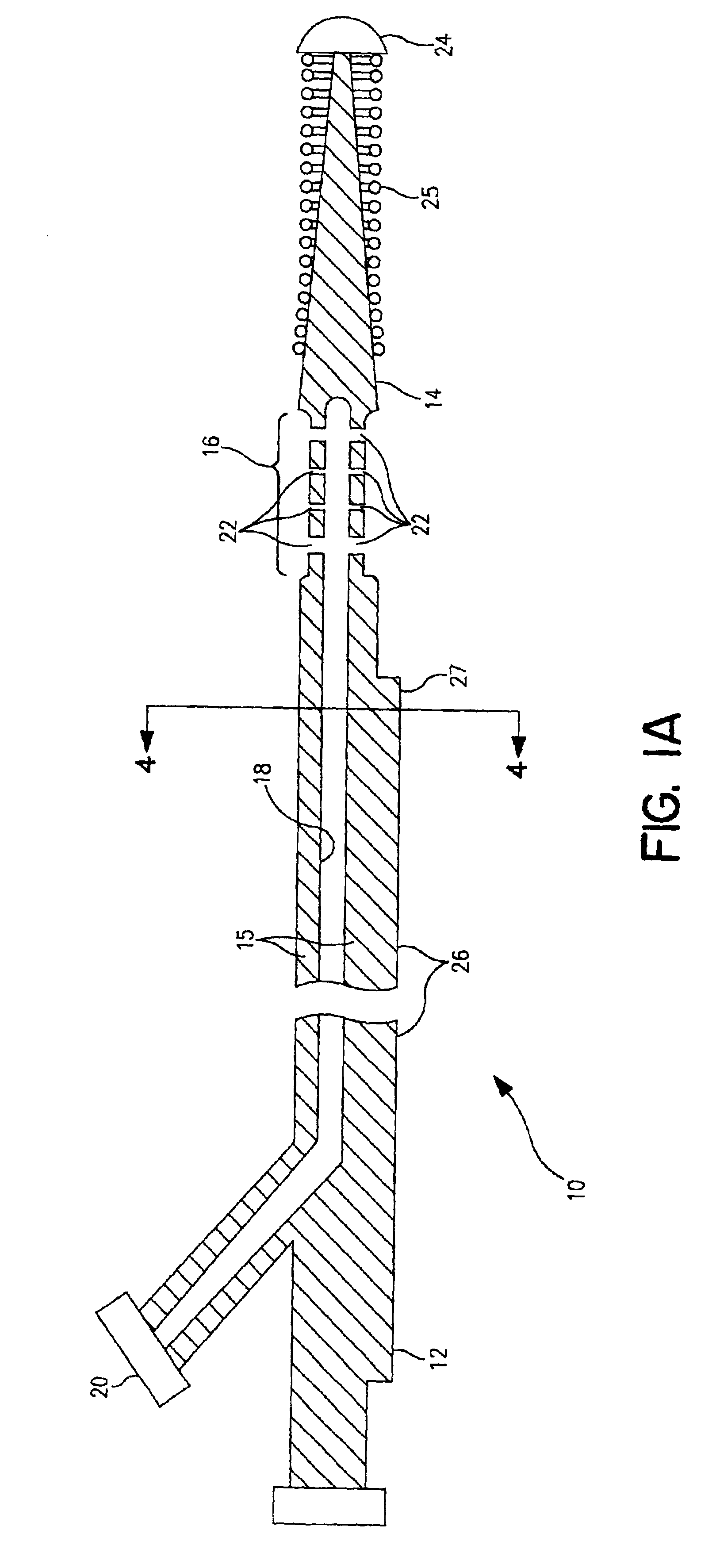
[0049]FIG. 1A is a cross-sectional side view of a guidewire 10 including a proximal end portion 12 and a distal end portion 14, which may be of a standard length of 175-310 cm long, or which may be of a non-standard length. The guidewire of the preferred embodiment has an elongated tubular body 15, and may have an outer diameter of between 0.014 and 0.038 inches at the proximal end portion. Preferably, the outer diameter of the proximal end portion ...


PUM


Abstract

An improved system and method for deploying medical electrical leads is disclosed. The system includes a guiding device such as a guidewire used to navigate the vascular system of a body. The guiding device includes a fixation member that can be deployed to maintain the guiding device at a desired location within the vascular system. The fixation member may be an inflatable device such as a balloon, or alternatively, may be an expandable device constructed of flexible fibers that has both an expanded and a contracted state. The system may further include a coupling member located adjacent to the guiding device. The coupling member may be a rail extending distally from a proximal end of the guiding device to a point proximal the fixation member. In an alternative embodiment of the invention, the coupling member is a channel included in the body of the guiding device adapted to slidably engage an electrode assembly. The coupling member is adapted to allow the electrode assembly to be slid to the distal end of the coupling member and deployed at a predetermined implant site. In one embodiment of the invention, the coupling member is movable with respect to the guiding device. This allows the coupling member to be re-positioned to multiple implant sites to deploy more than one electrode while the fixation mechanism remains stationary within a patient's vascular system. According to yet another aspect of the invention, the guiding device includes a lumen to delivery fluoro visible medium.

Description

RELATED APPLICATIONS[0001]This Application claims priority to provisionally-filed U.S. Patent Application Ser. No. 60 / 259,054 filed Dec. 29, 2000 entitled “System and Method for Placing Endocardial Leads”, which is incorporated herein by reference in its entirety.FIELD OF THE INVENTION[0002]The present invention relates generally to a system and method for placing one or more implantable cardiac leads within a coronary artery or cardiac vein; and more particularly, relates to using a guidewire to deploy one or more endocardial leads, wherein the guidewire includes a fixation means to retain the desired site of implant during the deployment process.BACKGROUND OF THE INVENTION[0003]Implantable medical electrical stimulation and / or sensing leads are well known in the fields of cardiac stimulation and monitoring, including cardiac pacing and cardioversion / defibrillation. In the field of cardiac stimulation and monitoring, endocardial leads are placed through a transvenous route to locat...

Claims


Application Information

Patent Timeline
Patent Type & Authority Patents(United States)
IPC IPC(8): A61N1/05
CPCA61N1/056A61N2001/0578A61N2001/0585
Inventor SUNDQUIST, STEPHENTHORNTON, ARNOLDDAHL, ROGERZYTKOVICZ, DUANEGARDESKI, KENNETH C.
Owner MEDTRONIC INC
Why Eureka
Try Eureka