Single Use Container Including a Collapsible Baffle Having Channels

a single-use container and baffle technology, applied in specific-use bioreactors/fermenters, biomass after-treatment, biochemical apparatus and processes, etc., can solve the problems of introducing contaminants into the processed liquid, tearing, abrasion, etc., to improve the anti-foam action, improve the mixing effect, and improve the effect of anti-foam action

Pending Publication Date: 2021-02-25
MILLIPORE CORP
View PDF0 Cites 1 Cited by
  • Summary
  • Abstract
  • Description
  • Claims
  • Application Information

AI Technical Summary

Benefits of technology

[0017]Improved methods for mixing a fluid or liquid in a container having an impeller assembly and a baffle placed in the container, the baffle comprising one or more channels / conduits for materials to be introduced into the container and / or for locating sensors within the container, are also disclosed. Some methods described herein comprise the delivery of a fluid into a container, wherein an impeller assembly is at least partially contained within the container and drives the blades or vanes of the impeller assembly to agitate the fluid in the container or bag. In some methods, the driver for the impeller assembly is external to the bag, and drives the impeller assembly magnetically. The baffle in the container improves mixing. In some methods, liquids and / or gases can be delivered through the channel(s) / conduit(s) of the baffle from the exterior of the container to a set point within the container and / or sensors can be located within the container at desired points, wherein measurements can be taken within at least one of a plurality of locations within the volume of the container.
[0018]Any and all embodiments of baffles and methods for processing using the baffles described herein are collapsible within the bag and may be expanded. When the baffles are at least partially expanded, the baffle(s) are capable of providing all functional features described herein. For example, this disclosure provides an integrated assembly that integrates channels / conduits for delivering various liquids and gases with the baffle(s) into a working volume of the container. The embodiments of the baffle(s) virtually eliminate piping or tubing typically required on a top of the bioreactor and / or the baffle(s) reduces the connection to the reactor to a lower portion of the reactor.
[0019]Also, any and all embodiments of baffles described herein facilitate the addition of various processing aids, e.g., antifoaming agents. For example, a conduit / channel of the baffle(s) is capable of delivering an anti-foaming agent onto the liquid surface of a, e.g., cell culture through a hole or a plurality of holes in the baffle(s). The hole(s) enable optimum placement and distribution of the antifoam agent, typically a liquid, in multiple places throughout the foam layer residing on the surface of the liquid being processed, wherein the effectiveness of the antifoam addition is increased. The hole(s) also permit better efficiency of antifoam action by allowing broader distribution of antifoam liquid at multiple locations on the liquid surface where foam accumulates. Also, as antifoam agents are distributed at multiple locations through a single baffle, i.e., less external tubing is required, saving manufacturing costs and / or set up times, simplifying the plumbing, i.e., the number of hoses, connectors, placement of hoses and connectors, etc., are reduced and easier to set up and operate. Any and all embodiments of baffles described herein reduce the number of separate tubes and connectors for delivering gas(es), feeds, and / or processing agents. Hoses and / or tubing for liquid / gas addition and / or venting typically run externally from the top of the bioreactor / bag / container, often extending to the user at ground level. Some bags may also include a form of internal hard piping to direct flow. These are typically single pipes or tubing lines tied together with tie wraps or some other means to make them manageable to the user. In a typical bioreactor application, many connections to the system are connected to the top of the bioreactor. Embodiments of the baffle(s) described herein comprise connections that are made to the lower part of the bag. Furthermore, the hose / tube connections described herein run into the top of the bag and are integral to the baffle and, therefore, eliminate the need for most external hoses / tubing. The integrated assembly of the bag and tubing described herein provide all the functionality of managing and organizing the tubing as well as bringing the interaction with the user to a lower or ground level, without external tubing reaching down from the top of the bag, combined with a baffle function.
[0020]Furthermore, the channels / conduits within the baffle enable a liquid feed to be delivered through the bag wall, up and / or through the baffle(s), and into the top of the reactor / bag. Also, the liquid feed can traverse the baffle(s) such that the feed is introduced to the cell culture in a high flow area (for example, near an impeller(s)). Delivering the liquid feed(s) below the liquid surface of the cell culture enhances mixing efficiencies. Delivery, for e.g., of an anti-foaming agent above the liquid surface enhances anti-foam agent efficiency. The baffle(s) having hole(s) permit faster mixing upon delivery because the feed is not necessarily dripped in at the liquid surface in a single stream.
[0021]Similarly, a first conduit or, optionally, a second conduit within the baffle(s) enables gas(es) to be introduced through the bag wall, and up the baffle to a head space at the top of the bag or bioreactor, i.e., above a fluid or liquid level within the bag. Gases can then exit via a port, which optionally comprises a vent filtration device. Incorporating these egress paths from the headspace through the bioreactor / bag container walls permits user interaction with the vent at a ground level (as opposed to requiring a ladder or step stool to reach the headspace area where vents are typically located). Also, sparge gases may be introduced into the wall of the bag and channeled to the baffle(s). Gas(es) may be introduced through a hole or plurality of holes in the baffle(s) to create an open pipe sparger or, alternatively, a ring-type sparger. The flow path is routed above the liquid surface, wherein an air break is created to prevent liquid from draining when the gases are not present, obviating the need for a check valve. The baffle having holes enables the manufacture of a sparger by putting a series of holes along one or both sides of the lowest horizontal baffle. This sparger can be manufactured for little to no extra cost. Gases may be delivered through filters as they enter the flowpath to assure sterility.
[0022]The shape of and / or the mounting points of the collapsible baffle enable it to collapse for shipping and storage while providing rigidity while the bioreactor or bag or mixer while in use. Optionally, rigid members may be placed within the baffle(s) to enhance rigidity.

Problems solved by technology

The sterilization procedures are expensive and cumbersome as well as being ineffectual at times.
Large volume bags, e.g., 1000 L to 2000 L volume bags, containers, or bioreactors, present challenges for incorporating a rigid baffle, because the increased height of these systems makes it difficult to introduce the rigid insert into the baffle sleeve, presenting potential failure modes, tearing, abrasions, introduction of contaminants into the processed liquid, etc.
In addition, the unfavorable bottom to top mixing evident in the smaller scaled bags becomes even more pronounced in larger bags because as the overall height of the bag increases, despite the reduced height to width aspect ratios, mixing efficiency decreases.
Unfortunately, the aluminum salts consist of particle sizes larger than 0.2 μm, and thus sterile filtering generally is not an option.
As a result, minimizing the number of containers into which the vaccine needs to be transferred, since each transfer represents a potential breach of sterility, and the resulting contamination can't be filtered away, is favorable.
Also, providing acceptable mixing, without imparting damaging shear effects, becomes more challenging as the size and / or aspect ratio of the bioreactor container increases.
However, higher shear rates associated with multiple impellers and / or high impeller speeds, as well as some baffles, can damage cells within the container.
However, this is an inefficient method for distribution in that the port is typically located along an inner surface of the container and distribution of the materials to where they are needed is often incomplete.
The dip tubes can create inconsistencies in the fluid flow in the bag, thereby complicating the mixing.
Moreover, placement of the sensors in dip tubes in the bag before use presents difficulties as the dip tubes are rigid plastic sleeves that cannot be packed as efficiently, making transport and storage of the bag less than optimal.
Furthermore, the use of sensors along the inner wall also limits the data that can collected and often what is occurring away from the inner wall of the bag must be inferred from the data obtained by the sensors, as opposed to direct measurements, which is an unfavorable method for data monitoring and collection.

Method used


Image

  • Single Use Container Including a Collapsible Baffle Having Channels
  • Single Use Container Including a Collapsible Baffle Having Channels
  • Single Use Container Including a Collapsible Baffle Having Channels

Examples


Embodiment Construction

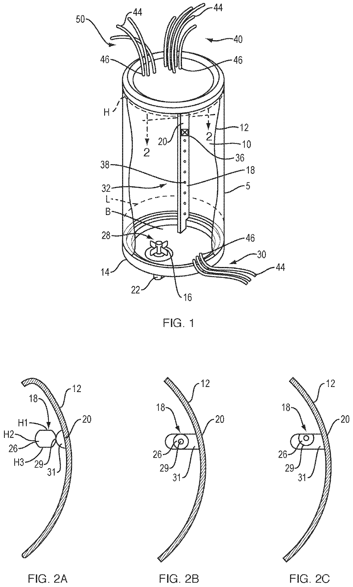
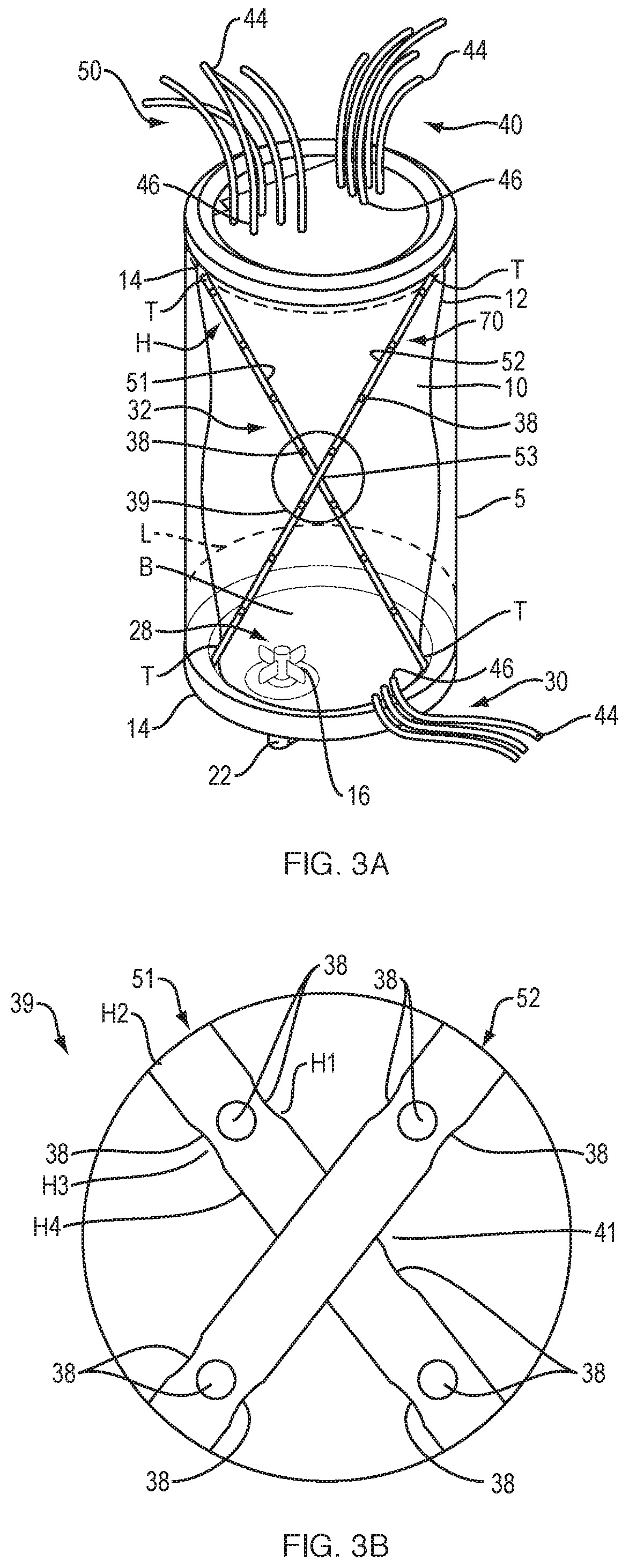
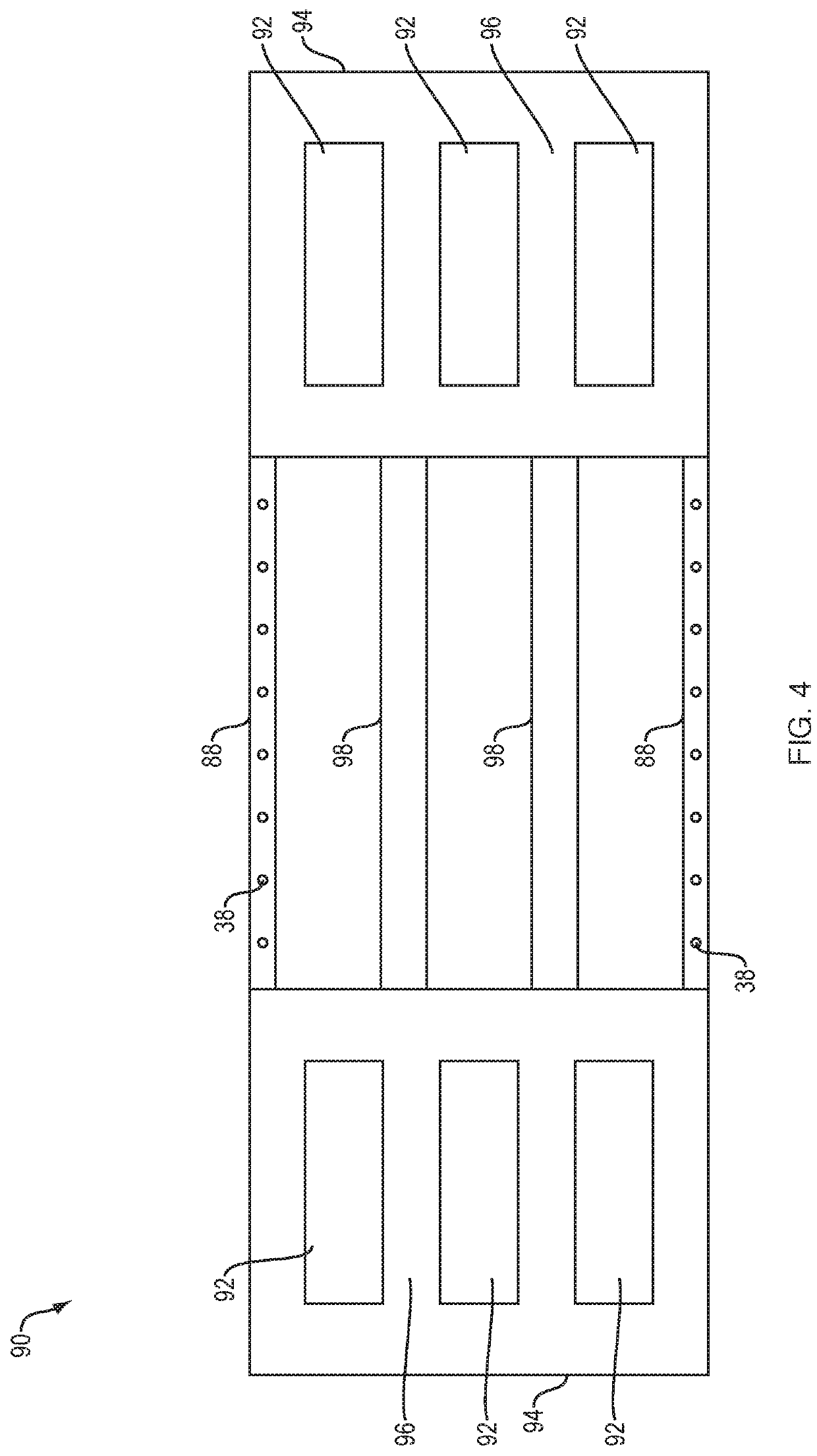
[0029]So the manner in which the features disclosed herein can be understood in detail, a more particular description of the embodiments of the disclosure, briefly summarized above, may he had by reference to the appended drawings. It is to be noted, however, that the appended drawings illustrate only typical embodiments of this invention and are therefore not to be considered limiting of its scope, for the invention may admit to other equally effective embodiments. It is also to be understood that elements and features of one embodiment may be found in other embodiments without further recitation and that, where possible, identical reference numerals have been used to indicate comparable elements that are common to the figures.

[0030]It is to be understood that recitation to a bag, container, and bioreactor refers to any flexible container capable of processing biological fluids, growing cells, fermenting, and the like and are used interchangeably throughout except where context dic...


PUM

PropertyMeasurementUnit
particle sizesaaaaaaaaaa
volumeaaaaaaaaaa
volumeaaaaaaaaaa

Abstract

A collapsible container for a fluid that includes a flexible material, defining an internal working volume; at least one collapsible baffle adhered within the working volume of said collapsible container, the at least one baffle having one or more channels for delivering one or more fluids into the working volume via at least one hole in said one or more channels, one or more channels in said container for exiting or venting fluids from the working volume, and an impeller assembly disposed at least partially within said working volume of said container.

Description

REFERENCE TO RELATED APPLICATIONS[0001]This present application claims the benefit of priority of U.S. Provisional Patent Application No. 62 / 655,277, filed Apr. 10, 2018, which is incorporated by reference herein in its entirety.BACKGROUNDField of the Invention[0002]Embodiments of the present disclosure relate to a collapsible container useful as a mixer or a bioreactor. More particularly, some embodiments disclosed herein include a collapsible baffle(s) having channels and holes formed within an interior portion of the baffle(s) for the delivery of liquids and / or gases within an inner volume of the collapsible container.Description of the Related Art[0003]Traditionally, fluids have been processed in systems that utilize stainless steel containers. These containers are sterilized after use so that they can be reused. The sterilization procedures are expensive and cumbersome as well as being ineffectual at times.[0004]To provide greater flexibility in manufacturing and reduce times n...

Claims


Application Information

Patent Timeline
Patent Type & Authority Applications(United States)
IPC IPC(8): C12M1/00C12M3/00C12M1/06C12M1/34
CPCC12M27/20C12M23/14C12M23/26C12M41/42C12M29/14C12M27/02C12M23/48C12M23/28C12M29/00C12M29/06C12M23/52
Inventor PEARSONS, JEFFREYWOOD, AMYKRAUS, DAVID
Owner MILLIPORE CORP
Why Eureka
Try Eureka