Lifting surgical instrument having branch point

a surgical instrument and branch point technology, applied in the field of surgical instruments, can solve the problems of increasing the difficulty of surgical scars, and increasing the time required for invasive methods

Active Publication Date: 2018-04-12
LEE JUN SUNG
View PDF4 Cites 1 Cited by
  • Summary
  • Abstract
  • Description
  • Claims
  • Application Information

AI Technical Summary

Benefits of technology

[0020]The indicator of the lifting surgical instrument having a branch point according to the present invention may include a body part and a cover part configured to be inserted over the body part. In this case, the body part may include a cylindrical base part and a screw part configured to extend from the base part and to include bolt threads, and screw grooves may be formed in the inner surface of the cover p

Problems solved by technology

The invasive method provides a desirable effect, but is disadvantageous in that the time required to perform the invasive method is relatively long, bleeding occurs during the process of directly making an incision, and surgical scars may be left.
First, the cogs or barbs of the thread 30 are formed on the sides of the thread 30, have directionality, and are formed in a wing shape through partial cutting. Accordingly, sufficient fastening force may not be provided via the cogs or barbs due to the thinness of the thread 30. The fastening force may be increased by increasing the thickness of the thread 30. When the thread 30 is thick, a patient may have the sensation of a foreign substance upon insertion into a skin tissue, thereby causing the patient discomfort. Although the fastening force may be increased by inserting a plurality of threads 30 into the skin, a plurality of insertion holes is thus required. Accordingly, a number of scars are left after a lifting surgery, thereby causing an aesthetic problem. Furthermore, as the number of threads 30 increases, the conventional technology becomes more

Method used


Image

  • Lifting surgical instrument having branch point
  • Lifting surgical instrument having branch point
  • Lifting surgical instrument having branch point

Examples


Embodiment Construction

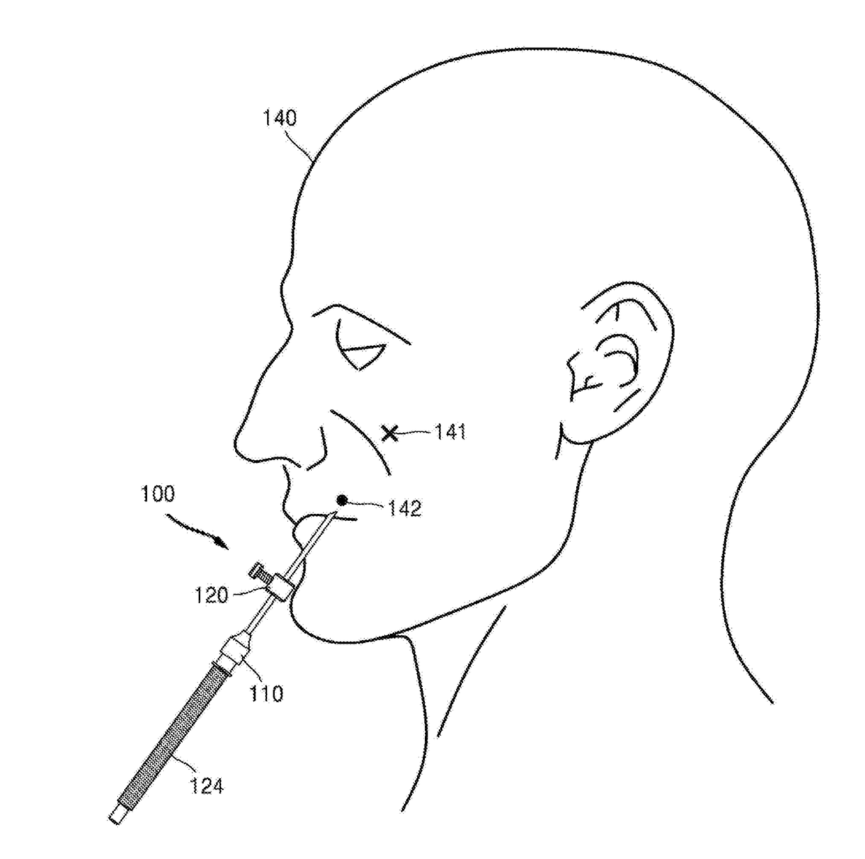
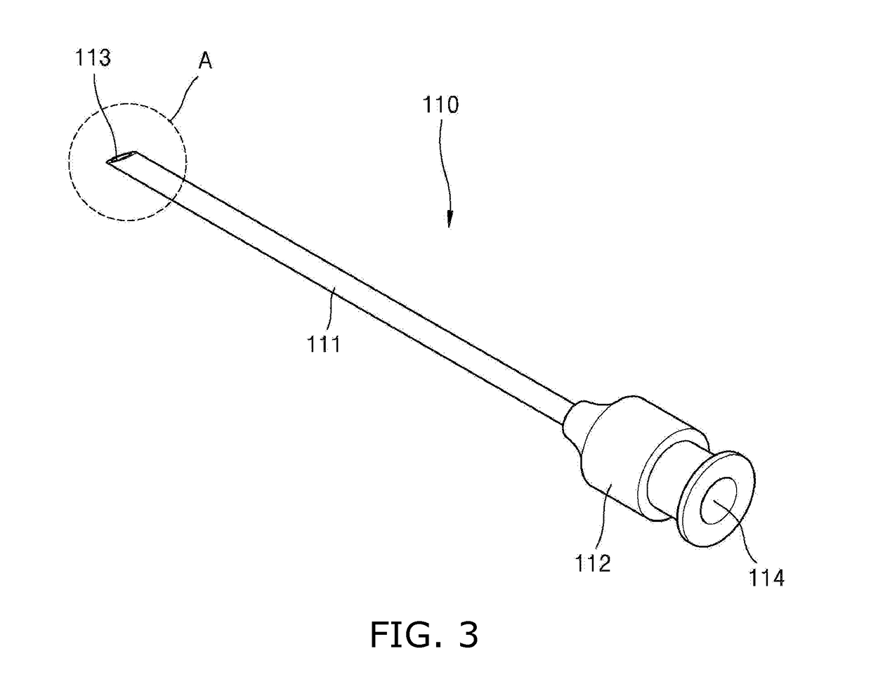
[0033]A lifting surgical instrument 100 according to the present invention is used to form a thread 131 without a cog and a barb in a ring shape under the skin and to perform a lifting surgery. The lifting surgical instrument 100 relates to a lifting surgical instrument having a branch point, which enables the front end of a sheath 110 to be disposed at a desired location in a subcutaneous tissue by using an indicator 120 and uses the sheath 110 as a branch point so that a thread 131 without a cog and a barb can be formed in a ring shape under the skin.

[0034]The lifting surgical instrument 100 according to the present invention is a surgical instrument for a surgical method which has been newly conceived by the applicant of the present invention. The newly conceived surgical method is configured to form the thread 131 without a cog and a barb in a ring shape at a desired location within the tissue and to lift a droopy tissue, unlike the conventional lifting surgical methods configur...


PUM


Abstract

Disclosed herein is a lifting surgical instrument having a branch point, which is used to insert a thread without a cog and a barb into the skin. The lifting surgical instrument includes a sheath, including: a probe part formed in the tubular shape in which a through hole penetrating in a longitudinal direction is formed, and configured such that the front end thereof may be inserted into the skin; and a body M configured to extend from the rear end of the probe part, to have a diameter larger than that of the through hole, to communicate with the through hole, and to include a sheath hole. In this case, a direction guidance portion is provided on the inner surface of the probe part, and the angle at which the needle travels is changed via the direction guidance portion when the needle passes through the through hole.

Description

BACKGROUND1. Technical Field[0001]The present invention relates to a lifting surgical instrument which is used to lift a tissue by moving a tissue layer under a skin layer in an upward direction or which is used to insert a thread into the skin in order to remove a wrinkle by moving a lower skin layer in an upward direction. More specifically, the present invention relates to a lifting surgical instrument having a branch point, which uses a sheath as a branch point in order to form a thread without a cog and a barb in a ring shape under the skin and to perform a lifting surgery.2. Description of the Related Art[0002]Generally, a plastic surgery is a generic term for surgical operations which are performed chiefly for the correction of a partially damaged or deformed part of a human body or for cosmetic treatment. Recently, surgical operations for cosmetic treatment have become commonplace. Among the surgical operations for cosmetic treatment, a surgical operation for anti-aging has ...

Claims


Application Information

Patent Timeline
IPC IPC(8): A61B17/34A61B17/04A61B90/00A61B17/06
CPCA61B17/3417A61B17/0482A61B17/3415A61B17/3478A61B90/02A61B17/3468A61B17/06109A61B2017/00477A61B2017/3454A61B2017/3409A61M25/0102A61B2017/00747A61B17/06166A61B2017/06052A61B17/00A61B2017/00792A61F2/0059A61B2017/00455A61B2017/06019A61B2017/06176A61M2025/009A61M2025/018A61B2090/036A61B2017/00969A61B2017/3405
Inventor LEE, JUN-SUNG
Owner LEE JUN SUNG
Why Eureka
Try Eureka