Retractable covering

a technology of retractable covering and bottom rail, which is applied in the direction of sliding/moving grilles, door/window protective devices, wing arrangements, etc., can solve the problems of unsightly gap between the bottom rail and the windowsill or floor, difficult to provide the proper length of lift cords between the head rail and the bottom rail for controlling drop, and limited full drop

Active Publication Date: 2018-01-09
HUNTER DOUGLAS IND BV
View PDF11 Cites 1 Cited by
  • Summary
  • Abstract
  • Description
  • Claims
  • Application Information

AI Technical Summary

Benefits of technology

[0014]Advantageously, the individual cord tensioner is readjustable. This allows the effective length of the lift cord to be adjusted as and when desired by a user post-installation.
[0016]Preferably all but one of the lift cords are provided with an individual cord tensioner. Alternatively, all of the lift cords may be provided with an individual cord tensioner. The individual cord tensioner preferably comprises a clamp which holds the cord at the desired tension. Alternatively the individual cord tensioner may comprise a slider which is manually movable along one of the rails, and which is attached to the lift cord, and a clamp may be provided on the slider to hold the slider at a desired location on the rail. The slider advantageously permits the cord to move in relation to the slider when the slider is in an unclamped state.

Problems solved by technology

On the other hand, for venetian blinds the full drop has usually been limited by the full extension of the lift cords.
Experience has shown, however, that providing the proper lengths of the lift cords between the head rail and the bottom rail for controlling drop has not been easy.
Accurate adjustment of drop is important because the bottom rail should not hit the windowsill or floor nor should it be suspended too high so that an unsightly gap exists between the bottom rail and the windowsill or floor.
However, it is not easy to precisely set the drop by adjusting the final location of a knot along the lift cords, at least prior to making the knot.

Method used


Image

  • Retractable covering
  • Retractable covering
  • Retractable covering

Examples


Embodiment Construction

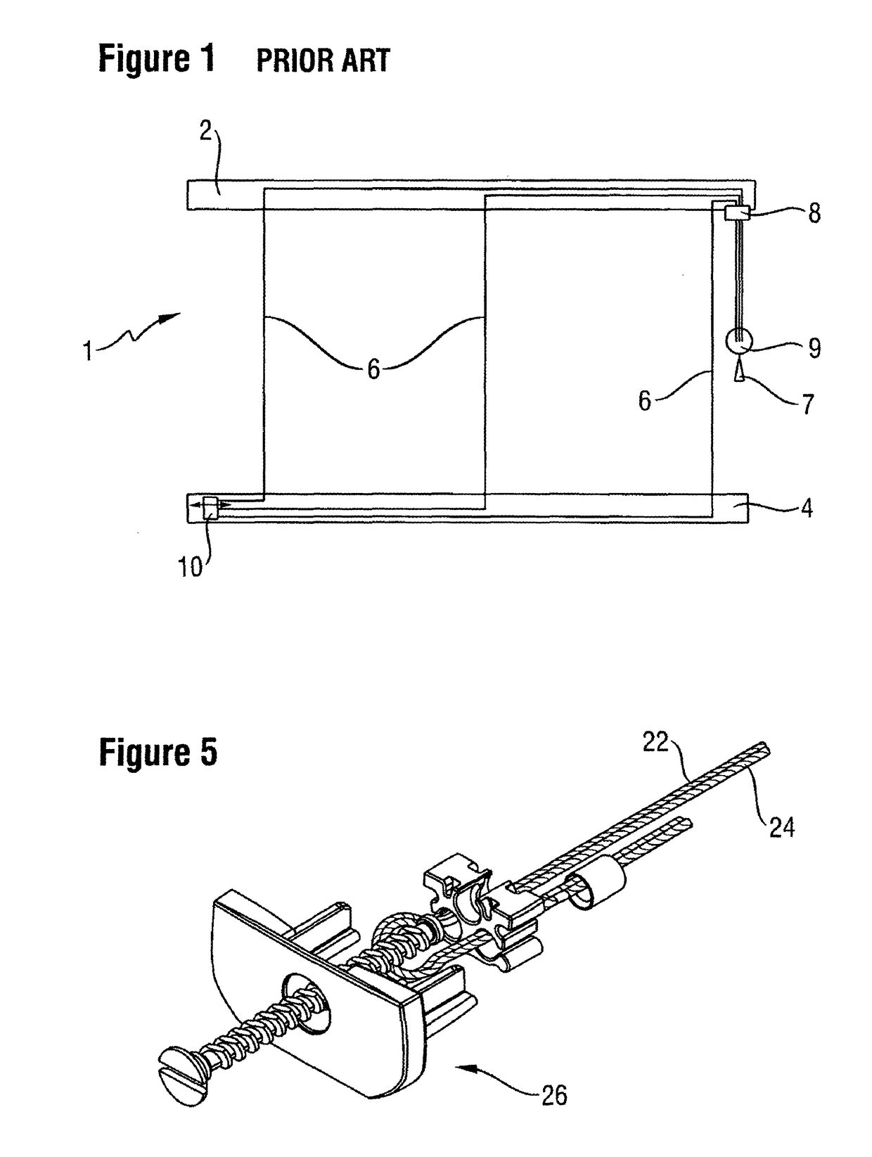
[0027]FIG. 1 shows a window blind 1 having a head rail 2 and a bottom rail 4. A shade fabric (not shown for clarity) extends between the head rail 2 and the bottom rail 4. Three lift cords 6 are provided for supporting the fabric, for raising and lowering the blind 1 and for supporting the bottom rail 4. The lift cord 6 also serves to limit the drop of the bottom rail 4. The lift cords 6 pass over conventional guide means in the head rail 2 and then out of the bottom of the head rail 2 through a cord lock 8. The cords are then connected by a conventional connector 9, from which a tassel 7 extends. A user can raise or lower the blind by pulling on the tassel 7.

[0028]The connector 9 also serves to limit the drop height of the blind 1 by limiting the downward movement of the bottom rail 4. In this regard, the connector 9 engages the cord lock 8 at the limit of the drop height, whereby the connector 9 cannot go outwardly any further and as a result, the bottom rail cannot go downwardly ...


PUM


Abstract

A retractable covering such as a door or window blind or shade has a top rail, a bottom rail, a covering material extending between the top rail and the bottom rail, at least two lift cords extending downwardly from the head rail to the bottom rail for supporting the bottom rail, a covering operating system for enabling retraction and deployment of the covering, and an adjuster connected to at least two of the lift cords. The adjuster is preferably mounted in the bottom rail. The retractable covering also comprises an individual cord tensioner for allowing at least one of the lift cords to be individually tensioned. The individual cord tensioner operates independently of the adjuster. A method of adjusting the orientation and drop height of the bottom rail of the retractable covering is also provided.

Description

CROSS-REFERENCE TO RELATED APPLICATIONS[0001]This application is the national stage application of International Patent Application No. PCT / NL2013 / 000011, filed Feb. 27, 2013, entitled “A Retractable Covering”, which claims priority to Netherlands Patent Application No. 2008370, filed Feb. 28, 2012, entitled “A Retractable Covering”, which are hereby incorporated by reference herein in their entireties.BACKGROUND OF THE INVENTION[0002]This invention relates to a retractable covering, particularly a covering for an architectural opening, such as a window or a door blind or shade.[0003]Conventional, blinds and shades for windows and doors include a head rail, a bottom rail, one or more window covering elements extending between the head rail and the bottom rail, at least two lift cords extending from the head rail and supporting the bottom rail, and a mechanism to limit the downward movement or drop of the bottom rail.[0004]For pleated or roman shades, the drop height of the shades ha...

Claims


Application Information

Patent Timeline
Patent Type & Authority Patents(United States)
IPC IPC(8): A47H5/00E06B3/94E06B3/48E06B9/06E06B9/388E06B9/322E06B9/382
CPCE06B9/322E06B9/388E06B9/382
Inventor FRANSSEN, JOHANNES ROBERTUS MARIA
Owner HUNTER DOUGLAS IND BV
Why Eureka
Try Eureka