Ratchet tool having improved driving shank

a technology of ratchet tool and driving mechanism, which is applied in the direction of wrenches, screwdrivers, manufacturing tools, etc., can solve the problems of not supporting a great rotational driving torque, no ratchet mechanism may be disposed in the driving member, and device is required, so as to facilitate the driving operation of the ratchet tool

Inactive Publication Date: 2005-08-30
CHEN SU SHIA
View PDF12 Cites 50 Cited by
  • Summary
  • Abstract
  • Description
  • Claims
  • Application Information

AI Technical Summary

Benefits of technology

[0011]The primary objective of the present invention is to provide a ratchet tool including an improved driving shank for facilitating the driving operation of the ratchet tool.

Problems solved by technology

However, the engagement between the radially or laterally moved pawls and the gear or the internal gear is weak, and thus may not sustain a great rotational driving torque.
However, no ratchet mechanisms may be disposed in the driving members, and a complicated retaining device is required to changeably attaché the shafts to the driving members.
However, the driving shanks or the driving stems may not be rotated relative to the handle, such that the driving tool may not be suitably used for driving some of the fasteners.

Method used


Image

  • Ratchet tool having improved driving shank
  • Ratchet tool having improved driving shank
  • Ratchet tool having improved driving shank

Examples


Embodiment Construction

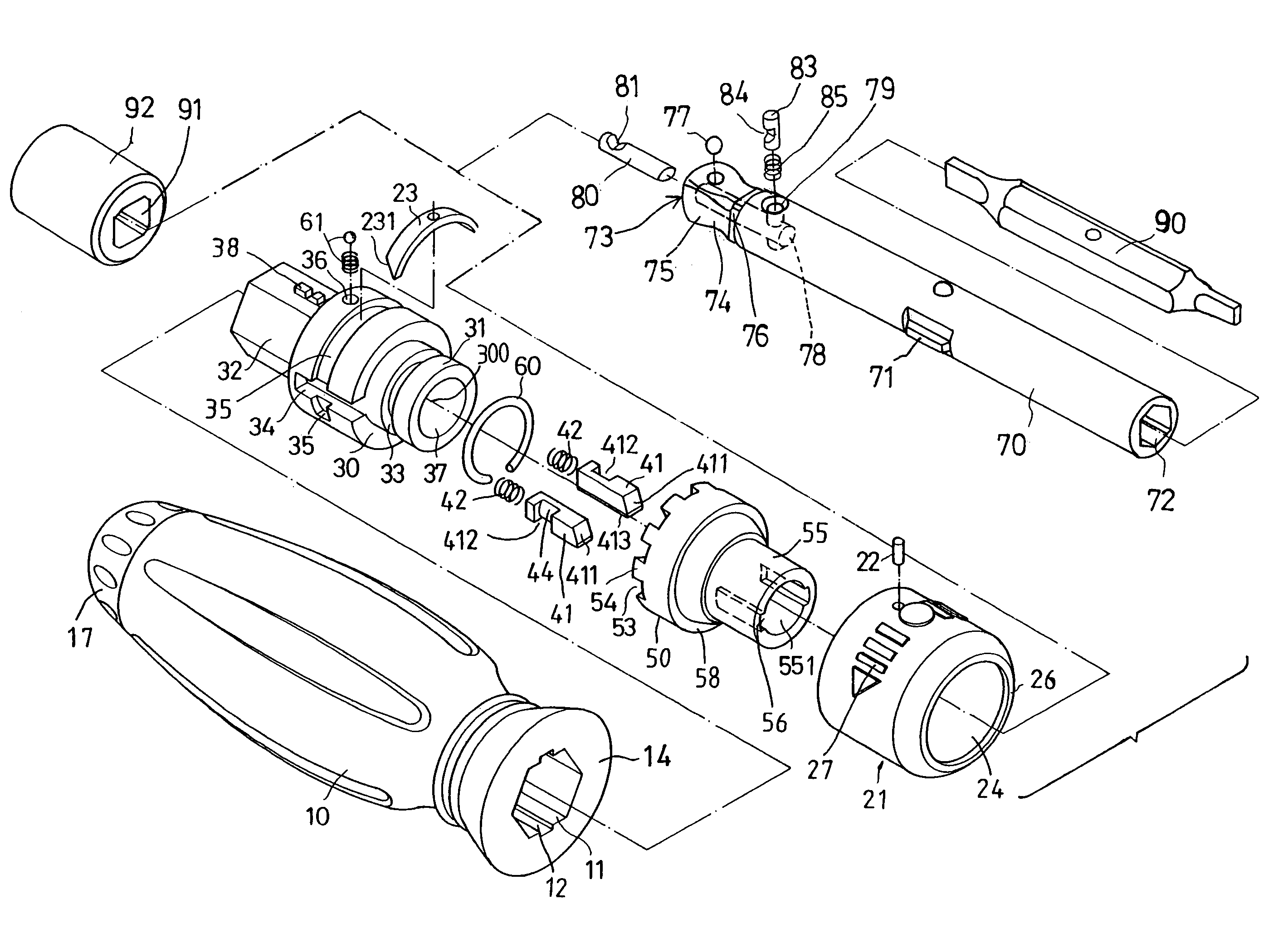
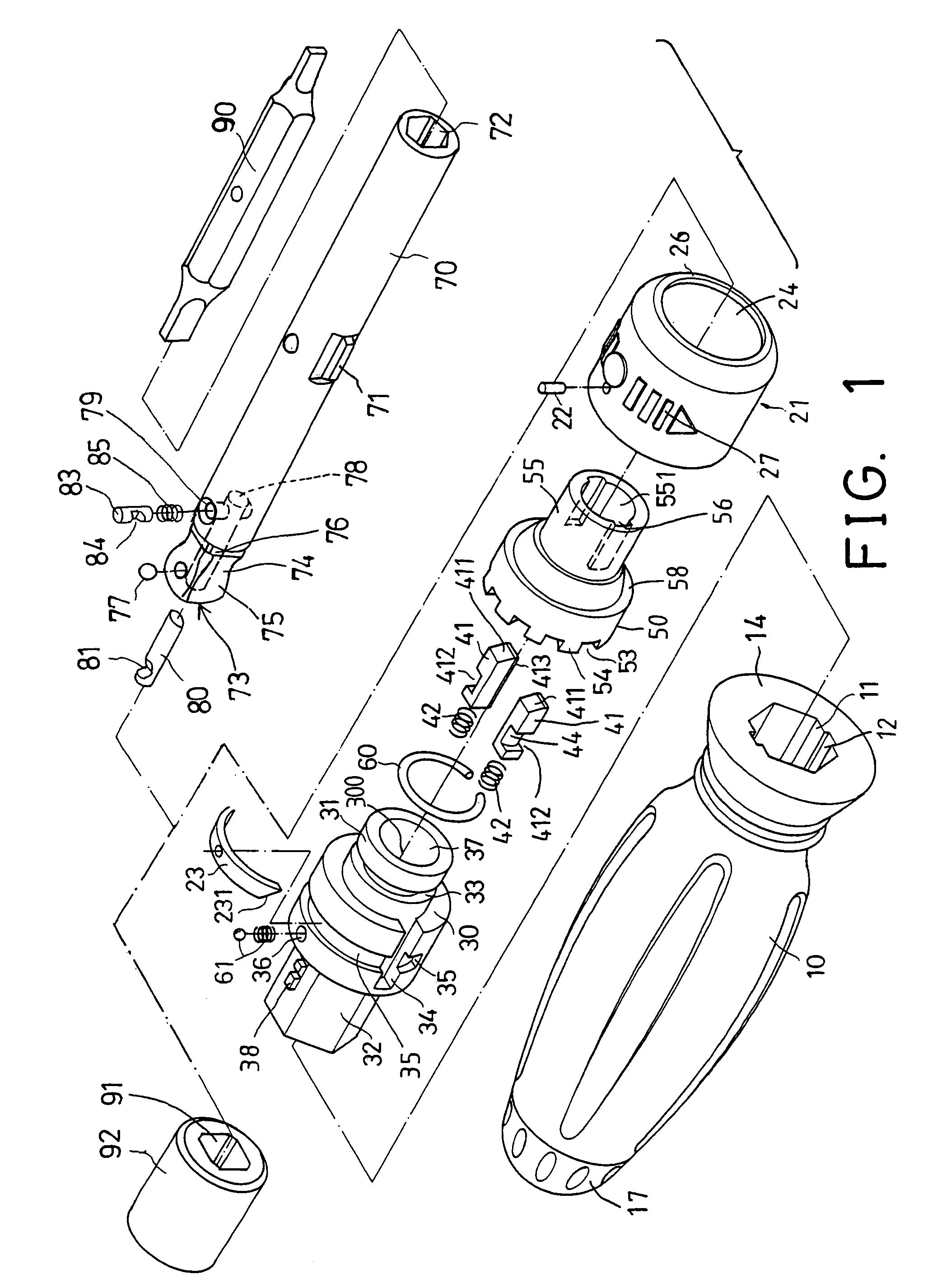
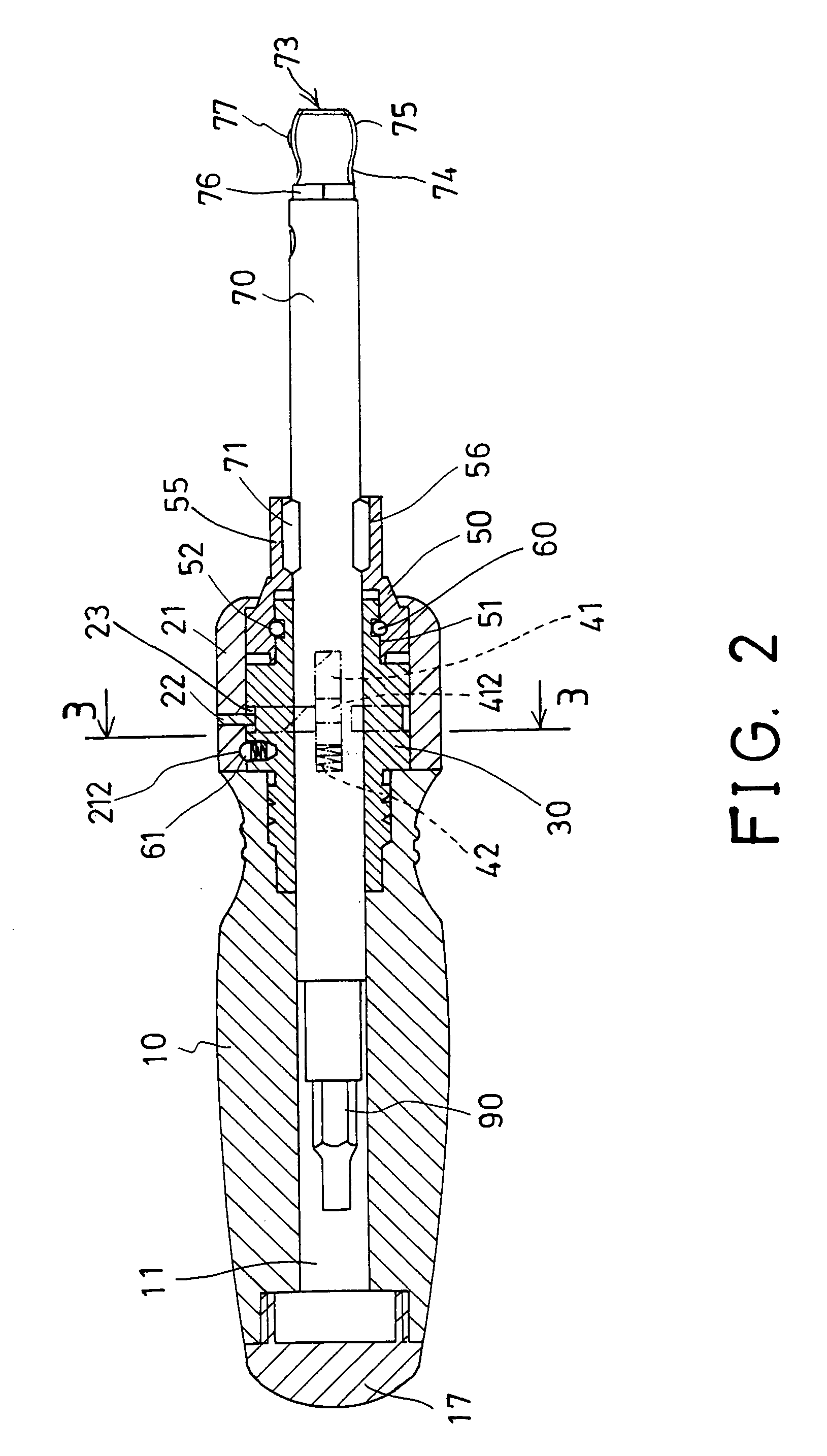
[0028]Referring to the drawings, and initially to FIGS. 1–5, a ratchet tool in accordance with the present invention comprises a handle 10 including a hole 11 and one or more slots 12 formed in one end thereof and communicating with each other and including a flat surface 14 formed in the end thereof. A cover 17 may be threaded to the rear end of the handle 10 to enclose the rear portion of the hole 11 of the handle 10.

[0029]A ratchet housing 30 is engaged with the flat surface 14 of the handle 10 and includes a bore 37 formed therein and includes an extension 32 extended from one end thereof and engaged into the hole 11 of the handle 10 and secured to the handle 10 with such as a force-fitted engagement, or the like.

[0030]The extension 32 and the mating hole 11 of the handle 10 include a mating non-circular cross section for allowing the housing 30 to be rotated in concert with the handle 10 and for allowing the housing 30 to be driven or rotated by the handle 10. The extension 32 ...


PUM


Abstract

A ratchet tool includes a seat rotatably secured to a housing and having a number of teeth, a driving stem is engaged in the seat and has an engaging hole to receive a tool member, two pawls are slidably engaged in the housing and biased to engage with the teeth of the seat. A device may selectively disengage the pawls from the teeth of the seat to control a rotational direction of the seat by the housing. The driving stem includes a narrower neck formed in the other end to form a head and to engage with and to drive tool elements. The provision of the narrower neck in the driving stem permits the driving stem to rotate relative to the tool elements.

Description

BACKGROUND OF THE INVENTION[0001]1. Field of the Invention[0002]The present invention relates to a ratchet tool, and more particularly to a ratchet tool having an improved driving shank for facilitating the driving operation of the ratchet tool.[0003]2. Description of the Prior Art[0004]Various kinds of typical ratchet tools have been developed and comprise an improved gear or internal gear and a pair of pawls moved radially or laterally toward the gear or the internal gear to control the operation directions of the ratchet tools.[0005]For example, U.S. Pat. No. 5,570,616 to Thompson et al., U.S. Pat. No. 5,687,820 to Lin, and U.S. Pat. No. 6,047,802 to Huang disclose three of the typical ratchet screw drivers each including a similar ratchet mechanism to control the operation directions of the ratchet screw drivers.[0006]However, the engagement between the radially or laterally moved pawls and the gear or the internal gear is weak, and thus may not sustain a great rotational drivin...

Claims


Application Information

Patent Timeline
Patent Type & Authority Patents(United States)
IPC IPC(8): B25B13/00B25B13/46B25B15/04B25B23/00B25G1/08
CPCB25B15/04B25B23/0028B25B23/0035B25G1/085
Inventor CHEN, SU SHIA
Owner CHEN SU SHIA
Why Eureka
Try Eureka