

Abrading mechanisms
a technology of abrading mechanism and abrading block, which is applied in the field of hand tools, can solve the problems of increasing the risk of injury, unable to meet the requirements of operation, and none of the currently known manual sanding blocks are of optimal design
- Summary
- Abstract
- Description
- Claims
- Application Information
AI Technical Summary
Benefits of technology
Problems solved by technology
Method used
Image

Examples
first embodiment
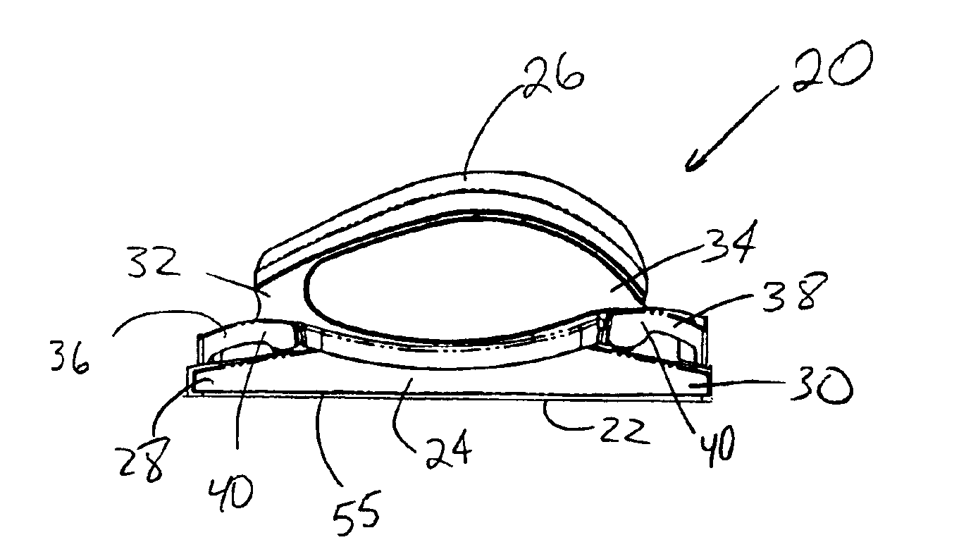
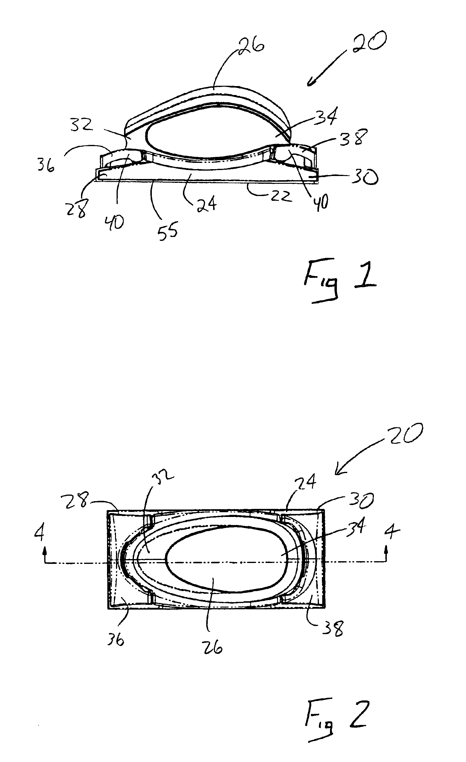
[0028]Referring now to the drawings, and with specific reference to FIG. 1, an abrading tool constructed in accordance with the teachings of the disclosure is generally referred to by reference numeral 20. One of ordinary skill in the art will readily recognize the general category of tool represented by the abrading tool 20 is that of sanding blocks. Such a block is adapted to hold replaceable sheets of sand paper or other abrading sheets 22 for refinishing or otherwise abrading a surface to be prepared (not shown). As used herein abrading tools are defined as any type of equipment used, to condition a surface through friction and accordingly would include sanders, polishers, scrubbers, or the like.
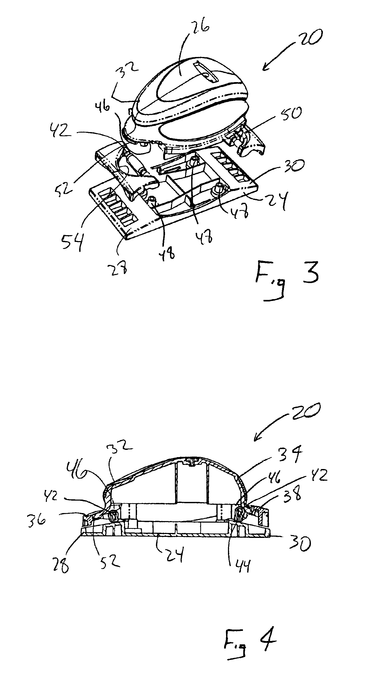
[0029]As shown best in FIG. 3, the abrading tool 20 includes a base 24 to which a handle 26 is secured. The base 24 includes first and second ends 28, 30. The handle 26 also includes first and second ends 32, 34. Mounted to each of the first and second handle ends 32, 34 are cam mechanis...
third embodiment
[0036]Turning now to FIGS. 7-11, an abrading tool constructed in accordance with the teachings of the disclosure is generally referred to by reference numeral 70. As shown therein, an abrading tool 70 includes a base 72 from which extends a handle 74 in a unitary fashion. First and second bridges 76, 78 connect the handle 74 to the base 70 to thereby provide a thru-hole 80 for receipt of a hand of the operator.
[0037]The abrading tool 70 further includes first and second ends 82, 84 to which are mounted first and second clamping mechanisms 86 and 88, respectively. Any number of different types of clamps 86, 88 may be employed with the preferred embodiment using one with a pivot arm 90 from which a pair of mounting struts 92 (FIG. 10) inwardly extend. An inner surface 94 of the pivot arm 90 further includes a spring recess 96, as well as first and second paper gripping teeth 98. Of course, in alternative embodiments, more than two teeth 98 can be provided. Regardless of the number of ...
fourth embodiment
[0039]Turning now to FIGS. 12-16, an abrading tool constructed in accordance with the teachings of the disclosure is generally referred to by reference numeral 120. As shown therein, the abrading tool 120 includes a base 122 to which is removably secured a cover 124. Preferably the base 122 is manufactured from a flexible or otherwise malleable material such as any number of thermoplastic elastomers such as those of the Santoprene® family of products, rubber, or the like. With specific reference to the exploded view of FIG. 14, the base 122 is shown to include a mounting hub 126 centrally located between first and second end flaps 128 and 130. Flexing grooves 132 are provided between the end flaps 128 and 130 and the mounting hub 126 so as to enable the base 122 to achieve any number of different configurations and thus enable a user to more readily apply abrasive force to the surface to be prepared.
[0040]Each of the end flaps 128 and 130 includes a plurality of recesses 134 adapted...
PUM
 Abstract
Description
Claims
Application Information