Image display method and image display unit

a technology of image display and image, applied in the field of image display method and image display unit, can solve the problem of large absolute value of change rate, and achieve the effect of accurate analysis

Inactive Publication Date: 2005-08-30
FUJIFILM CORP +1
View PDF5 Cites 0 Cited by
  • Summary
  • Abstract
  • Description
  • Claims
  • Application Information

AI Technical Summary

Benefits of technology

[0020]Preferably, the output brightness characteristic is approximately linear over approximately the entire intermediate signal value region, and the aforementioned change rate in the high signal value region is made greater. Furthermore, it is preferable that the output brightness characteristic be approximately linear over approximately the entire high signal value region. In this way, an image more similar in visual effect to the image in the case of outputting it to the aforementioned film can be displayed, even if there is an influence of ambient light.
[0024]In accordance with the present invention, there is provided an image display unit, which comprises a brightness circuit having an output brightness characteristic in which a logarithmic value of an output brightness becomes smaller as a value of an input image signal becomes greater, for displaying a visible image that the image signal represents according to the output brightness characteristic. In image display unit, the output brightness characteristic in the brightness circuit is set so that a rate of change, which represents a change in the logarithmic value of the output brightness with respect to a change in the signal value, in a low signal value region of the image signal becomes smaller than that in an intermediate and high signal value region of the image signal.
[0028]In the aforementioned image display unit of the present invention, the intermediate and high signal value region is similarly divided into an intermediate signal value region and a high signal value region. It is also preferred to make a change rate in the high signal value region greater than that in the intermediate signal value region. In this way, a reduction in a feeling of contrast of a displayed visible image, which is caused by the influence of ambient light, can be suppressed.
[0029]Preferably, the output brightness characteristic is approximately linear over approximately the entire intermediate signal value region, and the aforementioned change rate in the high signal value region is made greater. Furthermore, it is preferable that the output brightness characteristic be approximately linear over approximately the entire high signal value region. In this way, an image more similar in visual effect to the image in the case of outputting it to the aforementioned film can be displayed, even if there is an influence of ambient light.
[0033]The aforementioned image display method and image display unit of the present invention are more effective in the case where a medical image, particularly an image signal representing a radiation image, is employed as an input image signal.
[0034]According to the image display method and image display unit of the present invention, a rate of change in the logarithmic value of the output brightness in the low signal value region of an input image signal is made smaller than that in the intermediate and high signal value region of the image signal, and the image signal is displayed on a CRT display unit. etc. Therefore, the displayed image can be viewed as an image having the same visual effect as the case in which the image is output to X-ray film having a density characteristic in which a change rate of the density in the low signal value region is smaller than that of the density in the intermediate and high speed value region, and the transmitted light image is viewed with this X-ray film held to a light source or schaukasten.

Problems solved by technology

Likewise, a large change rate means that the absolute value of the change rate is large.

Method used


Image

  • Image display method and image display unit
  • Image display method and image display unit
  • Image display method and image display unit

Examples


Embodiment Construction

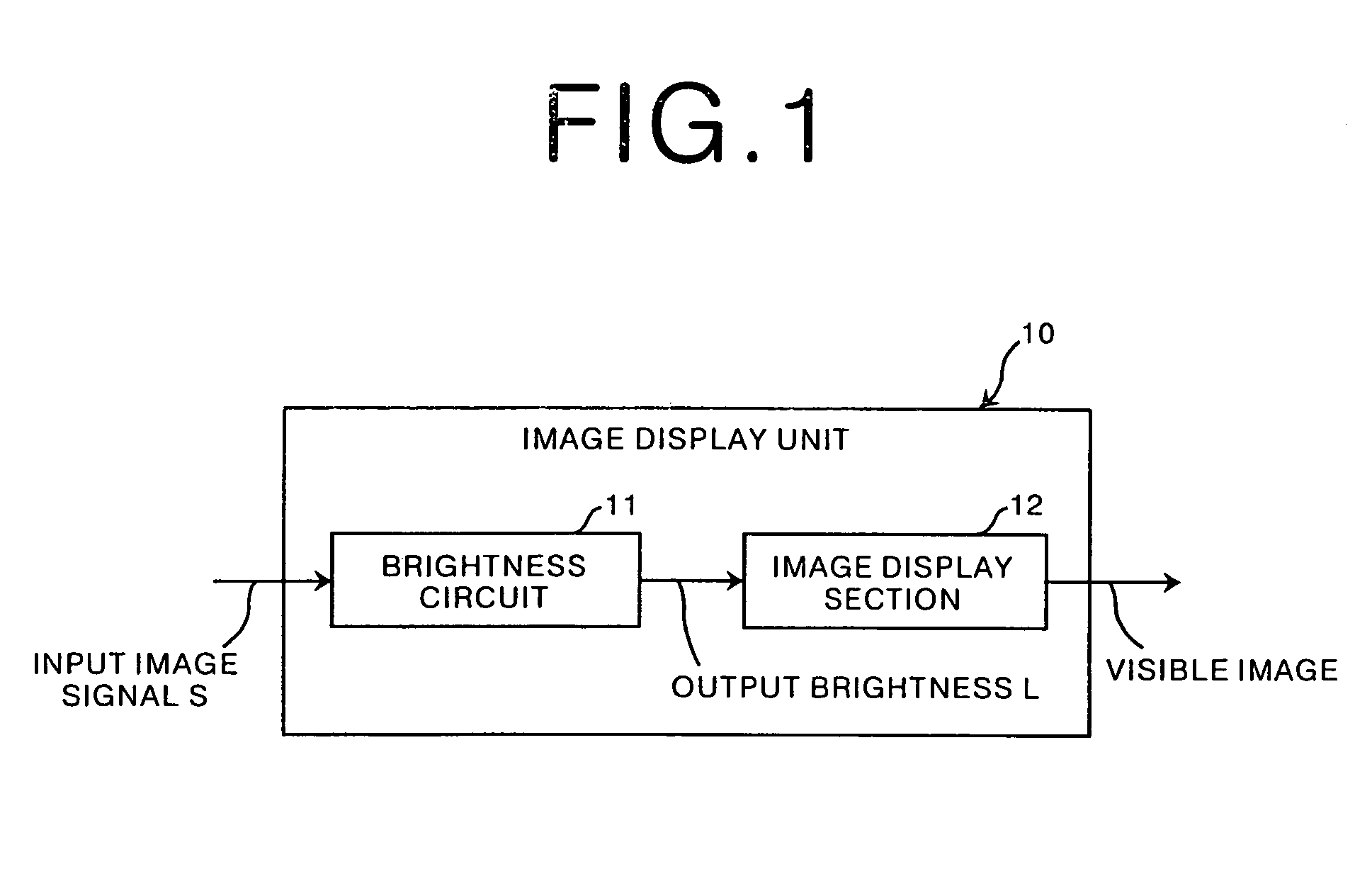
[0044]Referring to FIG. 1, there is shown an image display unit in accordance with a preferred embodiment of the present invention. The image display unit 10 is constructed of a brightness circuit 11 and an image display section 12. The brightness circuit 11 has an output brightness characteristic in which an input image signal S and its output brightness L are in a predetermined relationship. The image display section 12 visually displays an image that the input image signal represents in the brightness L output from the brightness circuit 11.

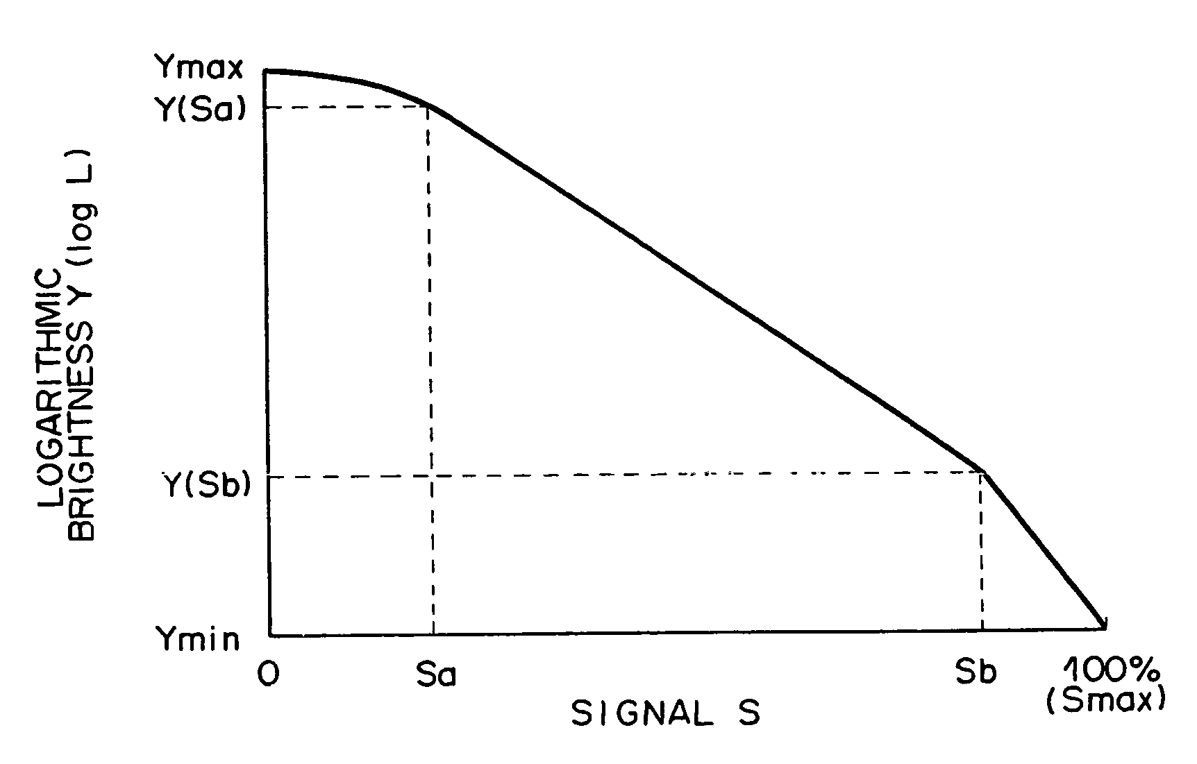
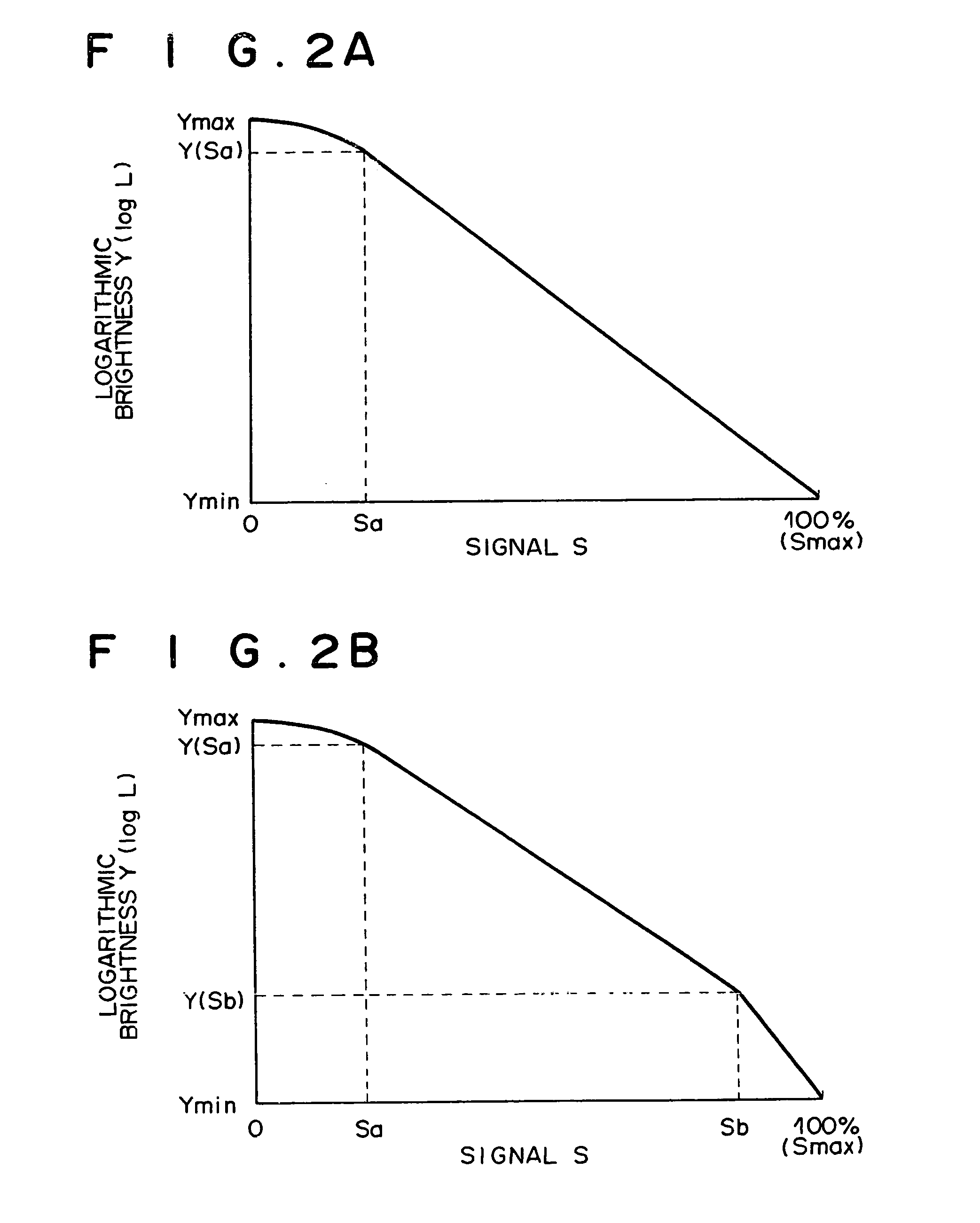
[0045]The output brightness characteristic of the brightness circuit 11 is a characteristic in which the logarithmic value Y (=log(L)) of the output brightness L becomes smaller as the value of the input image signal S becomes larger, as shown FIG. 2A. A rate of change |G0-a|(=|ΔY / ΔS|: absolute value of the differentiated value of Y with respect to the differentiated value of S), which represents a change in the logarithmic value Y of the outp...


PUM


Abstract

Disclosed herein is an image display unit comprising a brightness circuit which has an output brightness characteristic in which the logarithmic value of the output density of an input image signal becomes smaller as the value of the image signal becomes larger. The output brightness characteristic is set so that a rate of change, which represents a change in the logarithmic value of the output brightness with respect to a change in the signal value, in the low signal value region of the image signal becomes smaller than that in the intermediate and high signal value region of the image signal.

Description

BACKGROUND OF THE INVENTION[0001]1. Field of the Invention[0002]The present invention relates in general to an image display method and an image display unit, and in particular to an improvement in the output brightness characteristic between an input signal and its output brightness.[0003]2. Description of the Related Art[0004]In the medical field, a human body is irradiated with radiation, the radiation-transmitted image is recorded on X-ray film, and while the X-ray film recorded with radiation-transmitted image is being held to a light source or schaukasten (which is a box for observing X-ray film), the transmitted light image is observed and analyzed.[0005]On the other hand, because of the recent development of digital technology it is becoming standard to digitize and process the aforementioned radiation-transmitted image by computers. It has also become possible to observe and analyze the aforementioned radiation-transmitted image stored as a digital image on a server, etc., ...

Claims


Application Information

Patent Timeline
IPC IPC(8): G09G5/10
CPCG09G5/10
Inventor OGAWA, EIJI
Owner FUJIFILM CORP
Why Eureka
Try Eureka