Display device for a camera

a technology for a display device and a camera, which is applied in the field of display devices for a camera, can solve the problems of increasing the complexity of the interface with the user, difficult for a user to press the correct buttons, and the relative high cost of current displays, and achieves a more intuitive and convenient way of controlling the display of a region

Inactive Publication Date: 2005-08-30
XEROX CORP
View PDF15 Cites 105 Cited by
  • Summary
  • Abstract
  • Description
  • Claims
  • Application Information

AI Technical Summary

Benefits of technology

[0011]It would be desirable to provide a camera with an interface for reviewing stored images, which can provide an easier, more intuitive way of controlling the display of a region of an image.
[0013]This can provide a much more straightforward interface for the user, without the difficulty of finding, and trying combinations of buttons to control the display. It is also less fatiguing to the users.
[0014]In a preferred form, many of the image or display control operations are simply movements which the user would make if viewing the images through a lens or window. This can provide a highly intuitive manner of operation.

Problems solved by technology

This is a result of the relatively high cost of current displays, and the desire for compactness for a portable camera.
However, such an approach increases the complexity of the interface with the user.
It is often difficult for a user to press the correct buttons, or simultaneous combination of buttons, to provide an optimal path to the region of the image to be viewed.
The user may also have to take his or her eyes off the image to locate the desired control buttons, which makes the camera less convenient, and slower, to use.
Moreover, control buttons do not enable the user to control variably the scroll speed or the zoom speed.
However, this normally requires both hands if the user is holding the camera.
Touch screens can also be difficult to use particularly on small displays.
Additionally, a small display will usually be near the user's eye, which makes the display difficult to access with the finger.
However, such displays are more complex and expensive, and presently less reliable to use.

Method used


Image

  • Display device for a camera
  • Display device for a camera
  • Display device for a camera

Examples


example motion

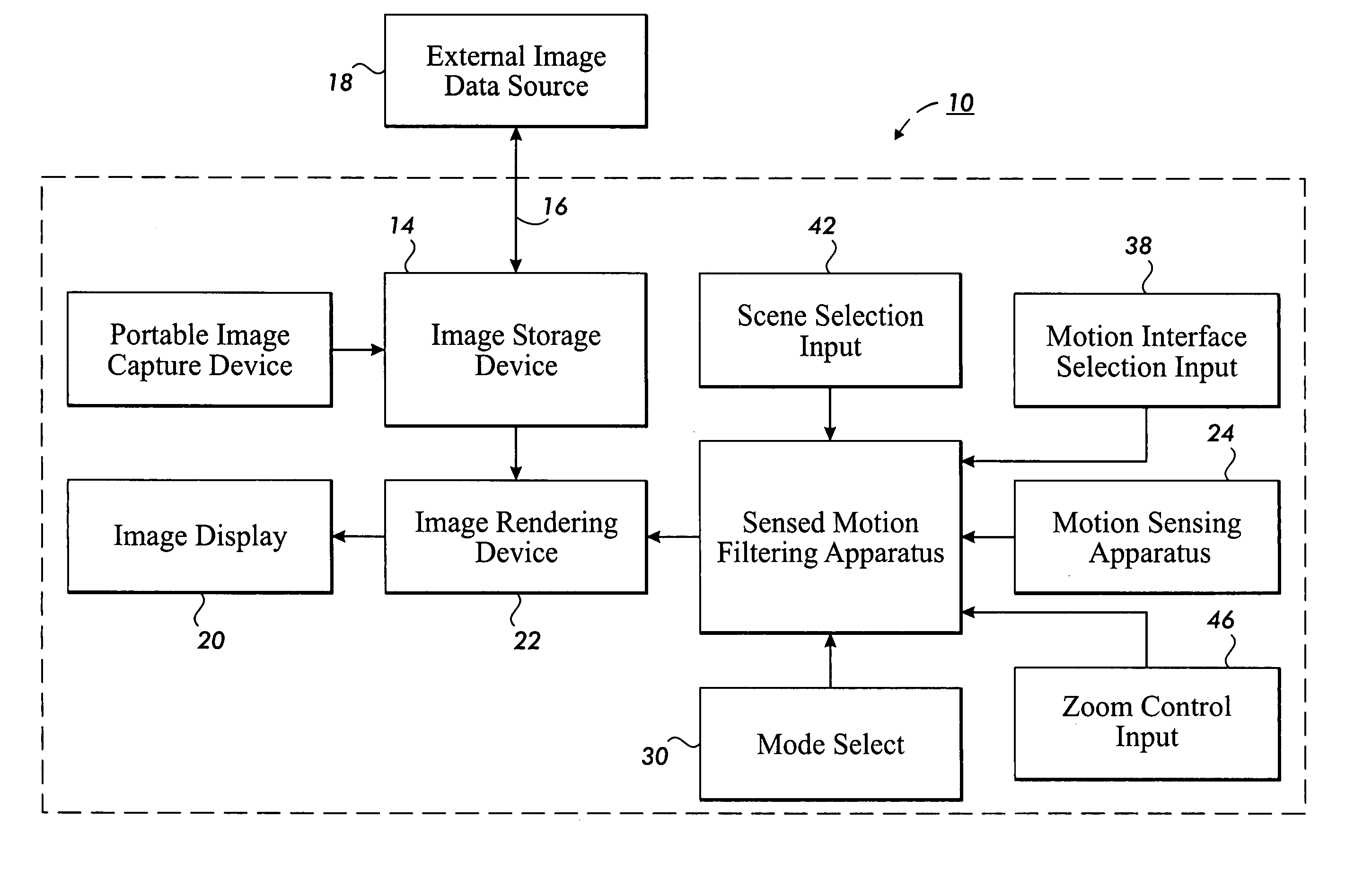
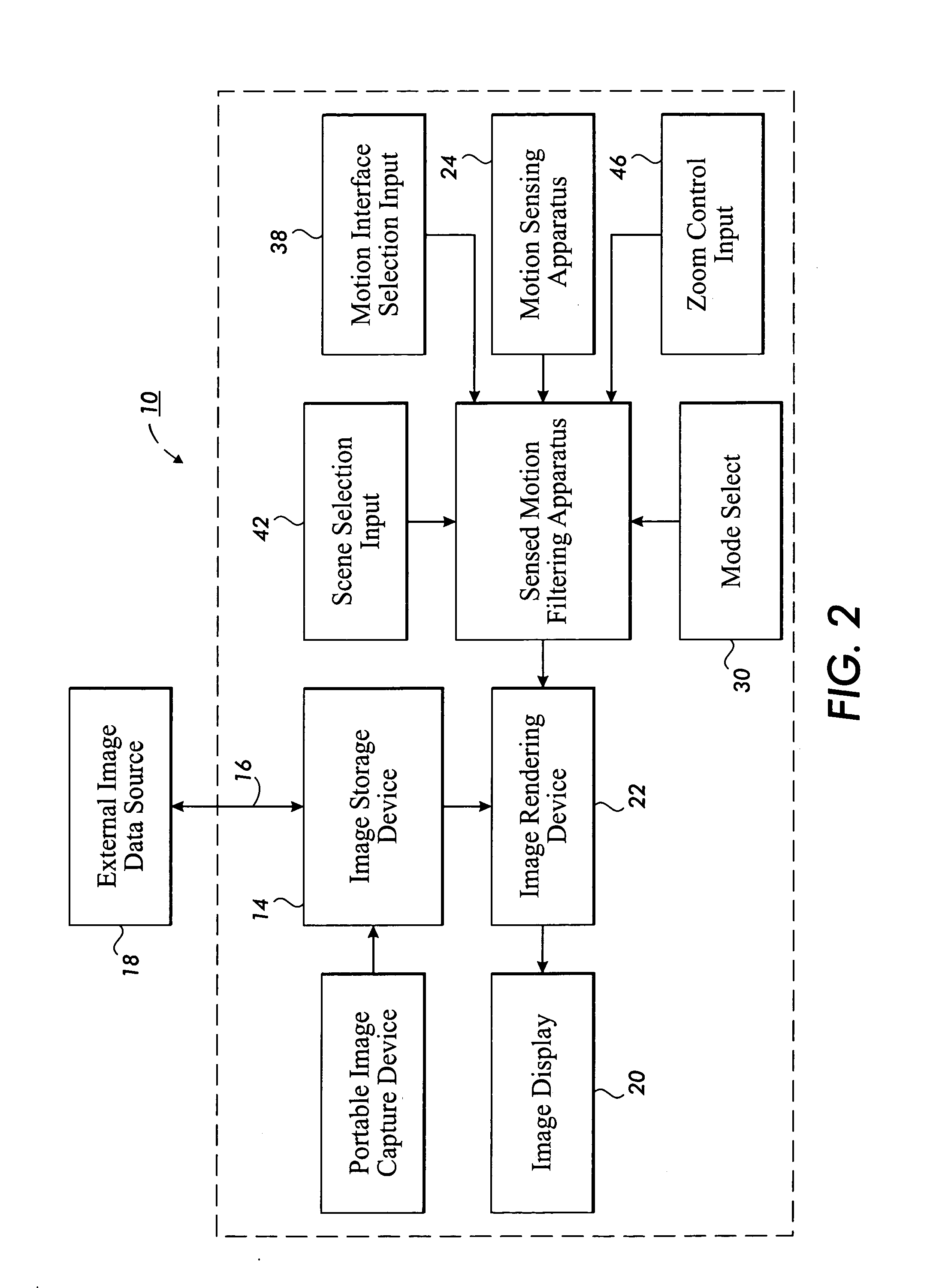
[0038 detection devices for detecting camera movement are described later.

[0039]The rendering circuit 22 also receives an input from a mode input device 30, in the form of a manually operable push button, for selecting one or more operating modes of the camera. In the present embodiment, the mode input device 30 is operable to initiate a scene selection mode, which causes the image rendering circuit 22 to generate the synthesized image selection scene for display on the display device 20. Referring to FIG. 3, the selection scene 32 consists of a plurality of icons or thumbnail views 34 representing the stored images. Each thumbnail view 34 may be a low-resolution rendering of the image it represents or, in the case of a video clip, a low-resolution rendering of a key image from the clip.

[0040]The selection scene 32 may be a one-dimensional (e.g. horizontal) array of the icons or thumbnail views or, as illustrated in FIG. 3, the selection scene 32 may be a two-dimensional array. The ...


PUM


Abstract

A camera is described having a display device for displaying one or more stored images after acquisition. The camera has a motion detector which enables the selection and / or display of a stored image to be controlled (at least partly) by physical movement of the camera. Scrolling (or panning) of an image in the display can be effected by moving the camera in a plane parallel to the plane of the camera display, or tilting the camera. Zooming can be effected by moving the camera is a direction generally perpendicular to the plane of the camera display. The movements are generally similar to those which the user would make if viewing the image through a window or lens, which leads to a highly intuitive manner of operation.

Description

BACKGROUND OF THE INVENTION[0001]1. Field of the Invention[0002]This invention relates to a display device for a camera, and to a method for controlling the display device. The invention relates in particular to a display device for displaying a stored image, for example, an image previously recorded by, and stored in, the camera.[0003]The invention is particularly, but not exclusively, suited to document image cameras, i.e. cameras adapted for imaging documents, rather than general photography cameras. However, the invention is applicable to all forms of camera (for example whether they be document cameras, or general digital cameras, or video cameras) in which a display device is provided for displaying a stored image.[0004]2. Description of Related Art[0005]The displays on hand held digital cameras, and hand held video cameras, tend to be small. This is a result of the relatively high cost of current displays, and the desire for compactness for a portable camera.[0006]Particularl...

Claims


Application Information

Patent Timeline
Patent Type & Authority Patents(United States)
IPC IPC(8): G06F1/16H04N5/232
CPCG06F1/1626G06F1/1694H04N1/00352H04N1/00442H04N1/00453H04N1/00461H04N1/00469H04N5/23293G06F2200/1637H04N2101/00H04N23/661H04N23/631H04N23/695
Inventor DANCE, CHRISTOPHER R.
Owner XEROX CORP
Why Eureka
Try Eureka