Eureka AIR delivers breakthrough ideas for toughest innovation challenges, trusted by R&D personnel around the world.

Matching peak velocities of acceleration and deceleration seek profiles in a disc drive

a disc drive and peak velocity technology, applied in the field of seek controllers, can solve the problems of large initial velocity error, high current inducing considerable noise and vibration in the disc drive, and approaching, but acoustically noisy

Inactive Publication Date: 2005-08-30
SEAGATE TECH LLC
View PDF25 Cites 16 Cited by
  • Summary
  • Abstract
  • Description
  • Claims
  • Application Information

AI Technical Summary

Benefits of technology

"The invention relates to a servo system that moves a head between a start and destination track based on a seek command. The system uses a calculator to calculate an adjustment factor based on the identified seek length and a representation of the current position of the head. The system selects a deceleration position-velocity profile and successive demand velocity values during the seek operation. The system also stores a plurality of deceleration and acceleration position-velocity tables to select the appropriate demand velocity for the actuator. The technical effect of the invention is to improve the accuracy and efficiency of the servo system in moving the head between tracks."

Problems solved by technology

Because the actual velocity of the actuator is at or near zero at the start of a seek and the demand velocity is at its peak, there is a large initial velocity error.
The high current induces considerable noise and vibration in the disc drive.
Employing a single lookup table from seek start to seek end is a simple approach, but acoustically noisy.
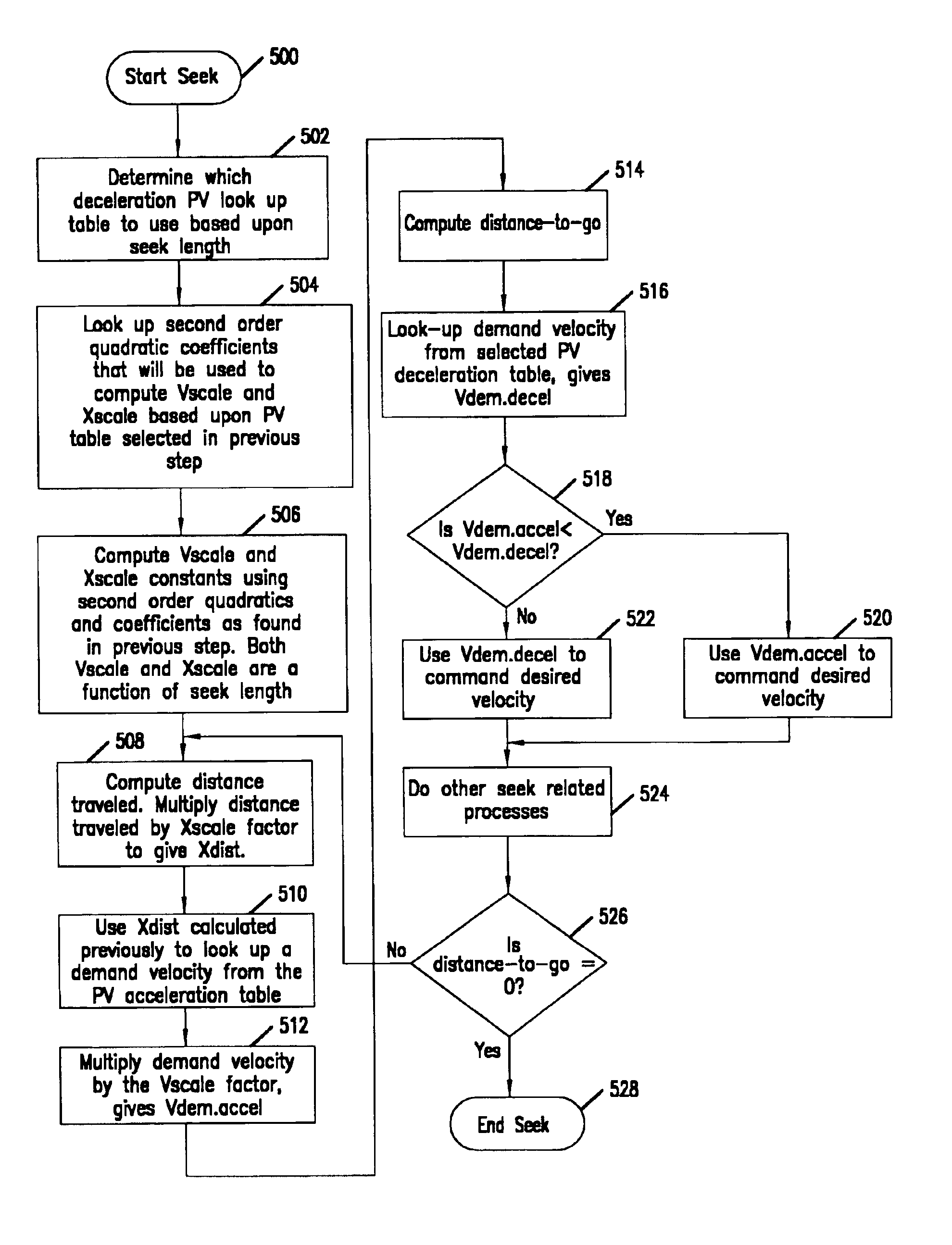
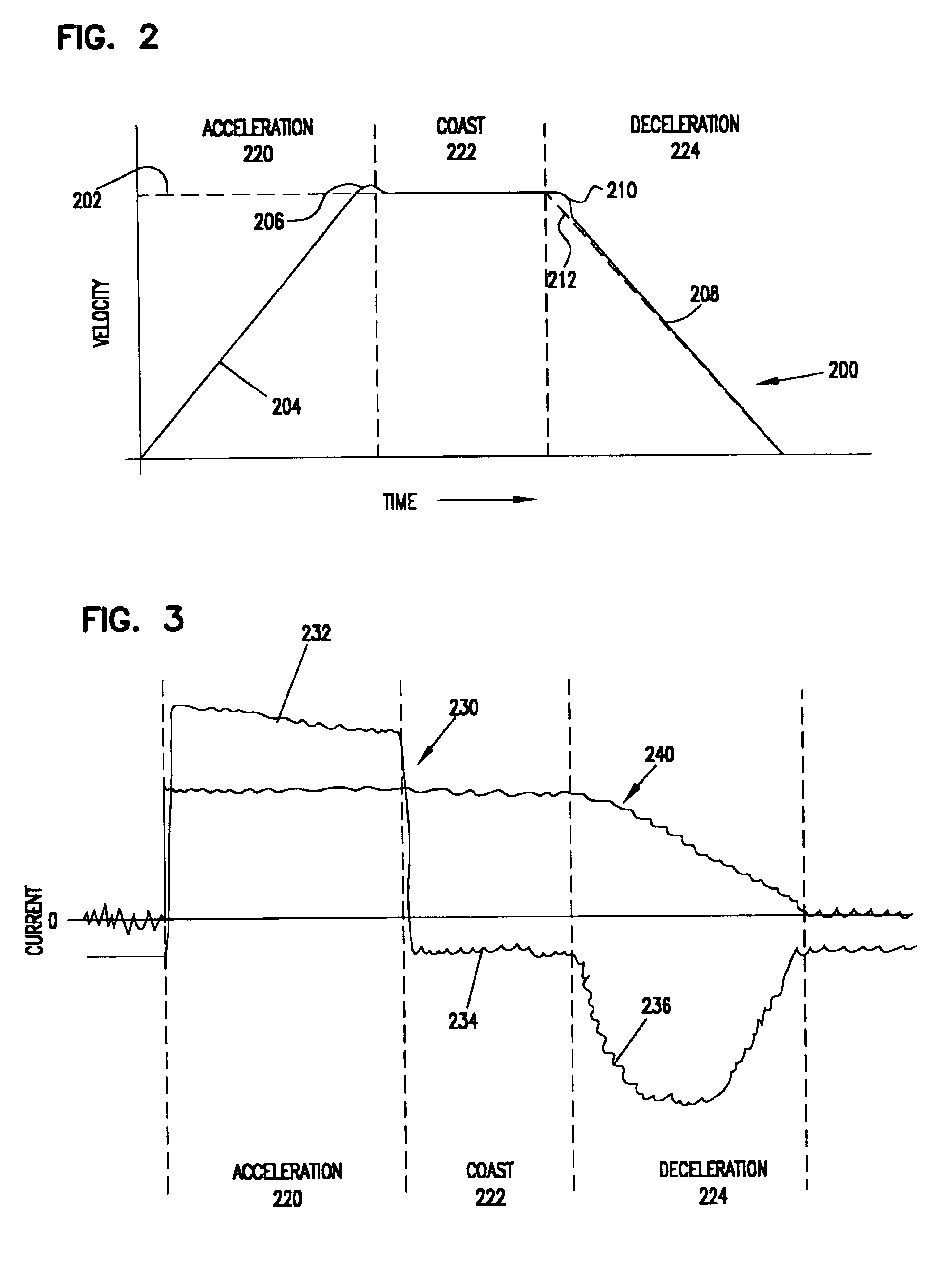
This change in demand velocity resulted in a mis-match of the peak velocities of the acceleration and deceleration phases, occasionally generating a noticeable noise that adversely affected operation of the disc drive.

Method used


Image

  • Matching peak velocities of acceleration and deceleration seek profiles in a disc drive
  • Matching peak velocities of acceleration and deceleration seek profiles in a disc drive
  • Matching peak velocities of acceleration and deceleration seek profiles in a disc drive

Examples


Embodiment Construction

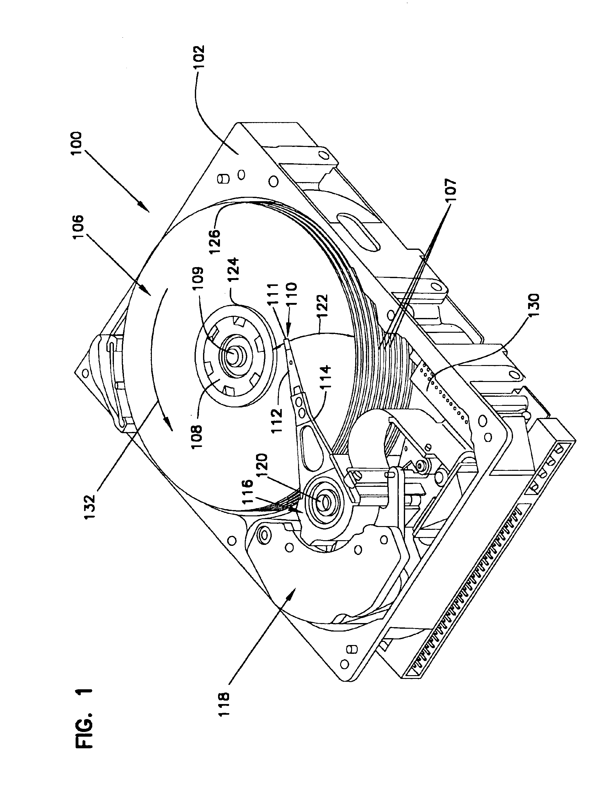
[0025]FIG. 1 is a perspective view of a disc drive 100 in which the present invention is useful. Disc drive 100 includes a housing with a base 102 and a top cover (not shown). Disc drive 100 further includes a disc pack 106, which is mounted on a spindle motor (not shown) by a disc clamp 108 for rotation in the direction of arrow 132. Disc pack 106 includes a plurality of individual discs 107, which are mounted for co-rotation about central axis 109. Each disc surface has an associated slider 110 that is mounted in disc drive 100 for communication with the confronting disc surface. Slider 110 is arranged to fly above the associated disc surface of an individual disc of disc pack 106, and carries a transducing head 111 arranged to write data to, and read data from, concentric tracks on the confronting disc surface. In the example shown in FIG. 1, sliders 110 are supported by suspensions 112 which are in turn attached to track accessing arms 114 of an actuator 116. Actuator 116 is dri...


PUM

PropertyMeasurementUnit
distanceaaaaaaaaaa
velocityaaaaaaaaaa
velocityaaaaaaaaaa

Abstract

A seek operation is performed by identifying a seek length of the seek operation and selecting a representation of a deceleration position-velocity profile based on the seek length. Successive demand velocity values are selected during the seek operation by identifying a distance-to-go and a distance-traveled of the seek length, calculating a representation of an acceleration demand velocity based on the identified distance-traveled and a representation of an acceleration position-velocity profile, identifying a representation of a deceleration demand velocity based on the identified distance-to-go and the selected representation of a deceleration position-velocity profile, and selecting the representation of either the acceleration demand velocity or the deceleration demand velocity. The representation of acceleration demand velocity is preferably performed by using a first scaling factors based on the seek length to adjust the identified distance-traveled, and using a second scaling factor based on the seek length to adjust a representation of a demand velocity of a normalized position-velocity profile.

Description

CROSS-REFERENCE TO RELATED APPLICATION[0001]This application claims priority of U.S. Provisional Application No. 60 / 371,032 filed Apr. 9, 2002 for “Noise & Vibration Reduction During Disk Drive Seek”.FIELD OF THE INVENTION[0002]This invention relates to disc drive data storage systems, and particularly to improved seek controllers for disc drives to reduce noise and vibration.BACKGROUND OF THE INVENTION[0003]Magnetic disc drive storage devices store digital data on rotatable magnetizable disc surfaces. Data are written to and read from concentric tracks on the disc by read and write transducers, usually called “heads”, that are supported by an actuator arm that positions the head relative to the tracks on the confronting disc. A voice-coil actuator motor rotates the actuator arm to move the head along an arcuate path generally radially across the disc. Actuator current applied to the actuator motor accelerates the rotational motion of the arm to move the head radially across the dis...

Claims


Application Information

Patent Timeline
Patent Type & Authority Patents(United States)
IPC IPC(8): G11B5/55
CPCG11B5/5526G11B5/5547
Inventor GALLOWAY, PAUL A.
Owner SEAGATE TECH LLC
Why Eureka
Eureka Blog
Learn More