Rear lighting device for motorcycles

Active Publication Date: 2005-09-06
YAMAHA MOTOR CO LTD
View PDF6 Cites 6 Cited by
  • Summary
  • Abstract
  • Description
  • Claims
  • Application Information

AI Technical Summary

Benefits of technology

[0008]The present invention has been made in view of the problems described above, and relates to a rear lighting device fo

Problems solved by technology

This results in a greater number of parts, and a more complicated mounting structure.
The use of a plurality of light emitting ele

Method used


Image

  • Rear lighting device for motorcycles
  • Rear lighting device for motorcycles
  • Rear lighting device for motorcycles

Examples


Embodiment Construction

[0044]A rear lighting device for a motorcycle in accordance with an embodiment of the present invention will be described below with reference to the accompanying drawings.

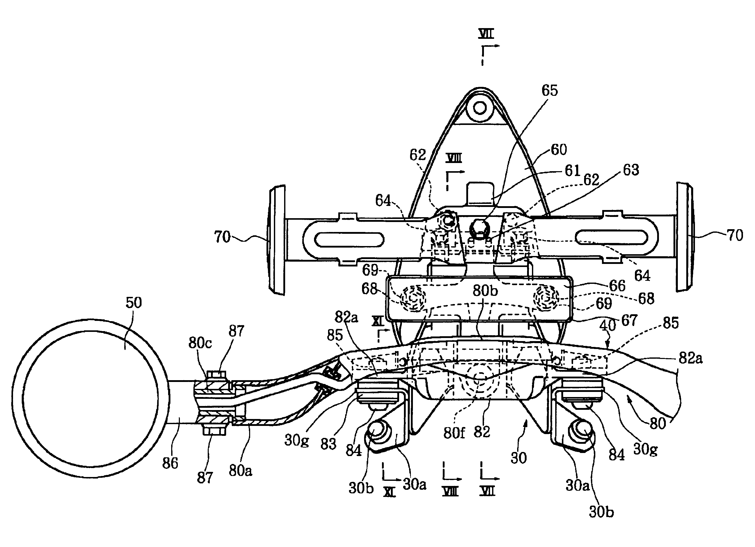
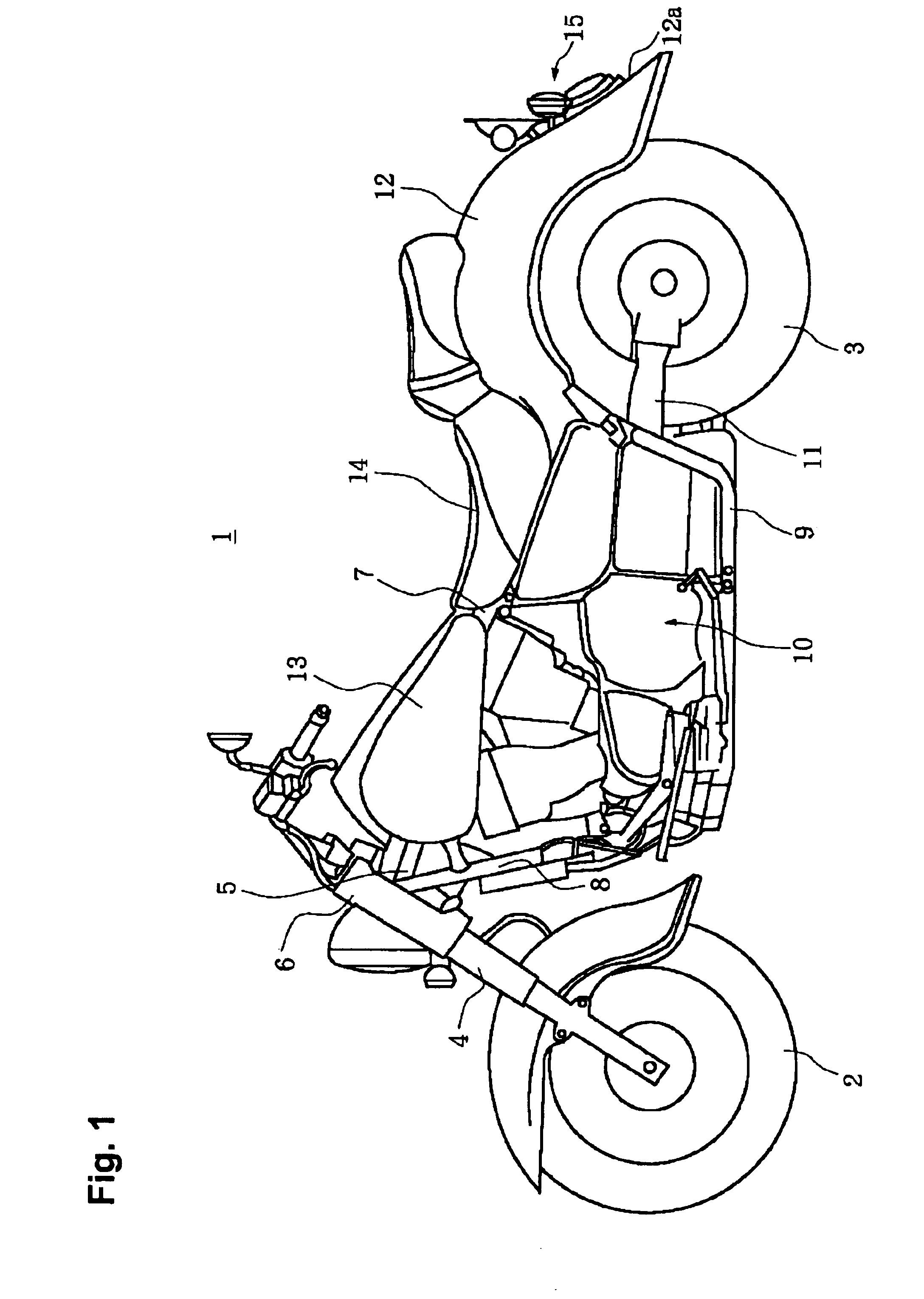
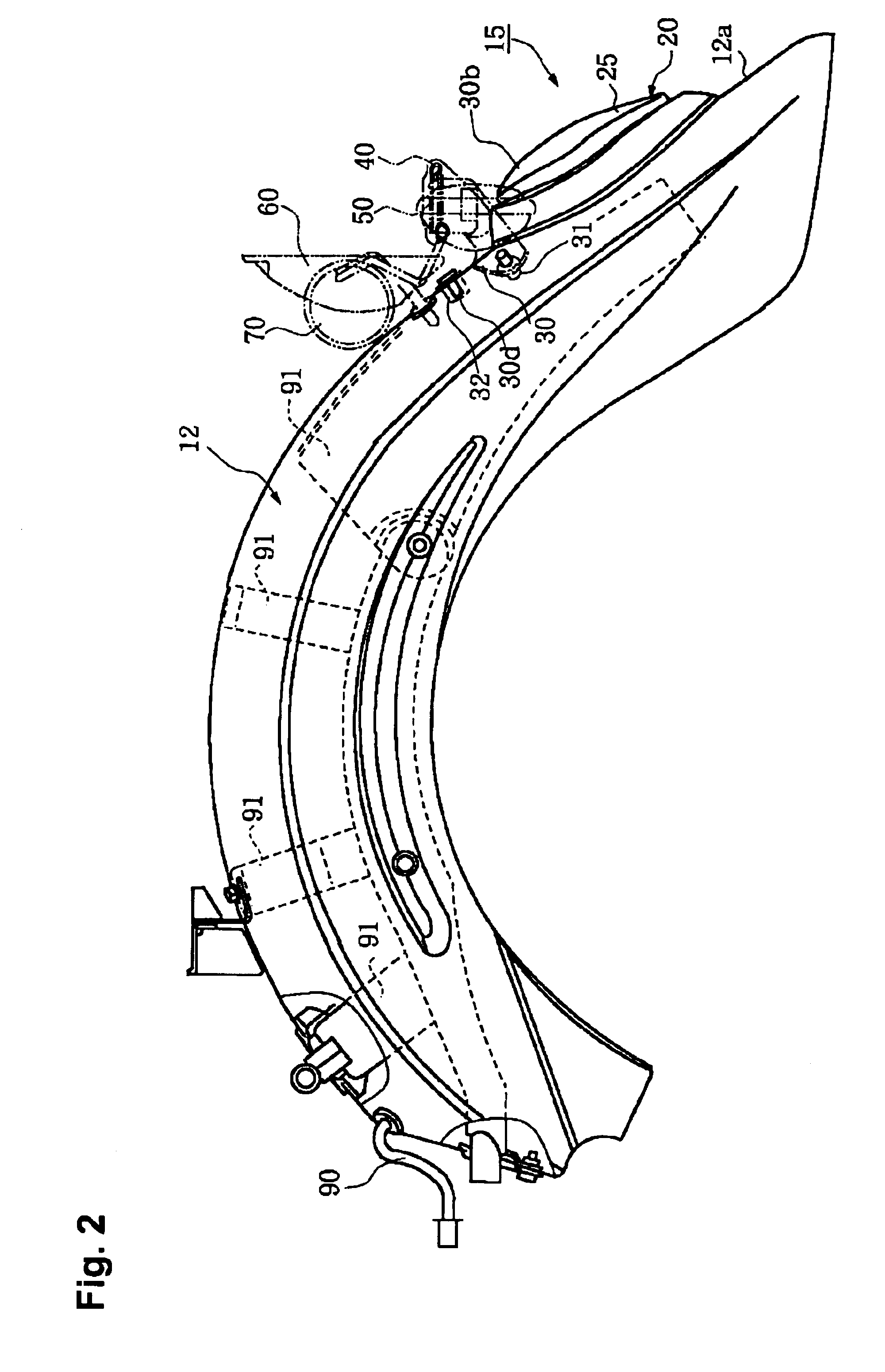
[0045]FIG. 1 is a side view of a motorcycle. FIG. 2 is a side view of a rear fender with a tail lamp mounted thereon. FIG. 3 is a plan view of the rear fender without a tail lamp. FIG. 4 is a rear view of a rear lighting device in accordance with an embodiment of the present invention. FIG. 5 is a bottom view of the rear lighting device. FIG. 6 is a side view of the rear lighting device. FIG. 7 is a cross-sectional view taken along lines VII—VII of FIG. 4. FIG. 8 is a cross-sectional view taken along lines VIII—VIII of FIG. 4. FIG. 9 is a cross-sectional view taken along lines IX—IX of FIG. 6. FIG. 10 is a cross-sectional view taken along lines X—X of FIG. 6. FIG. 11 is a cross-sectional view taken along lines XI—XI of FIG. 4. FIG. 12 is a side view of a stay bracket. FIG. 13 is a plan view of the stay bracket. FI...


PUM


Abstract

A rear lighting device for a motorcycle is disclosed. The rear lighting device is mounted on a rear fender that covers a rear wheel of the motorcycle. The rear lighting device includes a flasher stay that is mounted on the rear fender through a stay bracket, and flashers mounted on right and left mounting end sections of the flasher stay. The flasher stay includes a mounting plane surface section provided in a generally central area of the flasher stay along its length direction and right and left end sections on both sides of the mounting plane surface section. The mounting plane surface section is defined by a plate like section that is generally flat in a direction perpendicular to the length direction of the flasher stay, and the mounting plane section extends generally horizontally as the flasher stay is mounted on the stay bracket.

Description

BACKGROUND OF THE INVENTION[0001]1. Field of the Invention[0002]The present invention relates to rear lighting devices for vehicles such as motorcycles.[0003]2. Related Background Art[0004]A motorcycle may be equipped with a tail lamp mounted on a rear fender that covers a rear wheel. A plurality of light emitting elements may be used in the tail lamp.[0005]Also, a motorcycle may be equipped with flashers mounted on both right and left ends of flasher stays that are made up of round pipes, and the flasher stays are mounted on a rear fender by a holder.[0006]When the flasher stays made up of round pipes are used, a mounting state in which the flasher stays are mounted on the rear fender needs to be hidden from view by the holder which is an independent part. This results in a greater number of parts, and a more complicated mounting structure.[0007]The use of a plurality of light emitting elements for the tail lamp may entail some problems. For example, the tail lamp cannot illuminate...

Claims


Application Information

Patent Timeline
IPC IPC(8): B62J6/00B62J11/00B62J15/00B62J6/04B62J99/00
CPCB62J6/04B62J11/00B62J15/00
Inventor MIYAMOTO, TAKEHIRO
Owner YAMAHA MOTOR CO LTD
Why Eureka
Try Eureka