Modular plug-in electrical wiring system

a plug-in and plug-in technology, applied in the direction of coupling device details, coupling device connections, electric discharge lamps, etc., can solve problems such as people's injuries

Inactive Publication Date: 2005-09-06
KIEFFER JR DON J +1
View PDF6 Cites 80 Cited by
  • Summary
  • Abstract
  • Description
  • Claims
  • Application Information

AI Technical Summary

Benefits of technology

[0010]Another feature of the invention is the provision of a pair of matable modular units that ...

Problems solved by technology

Typically, electrical wall outlets and switches can exhibit a tangled mess of electrical wires w...

Method used


Image

  • Modular plug-in electrical wiring system
  • Modular plug-in electrical wiring system
  • Modular plug-in electrical wiring system

Examples


Embodiment Construction

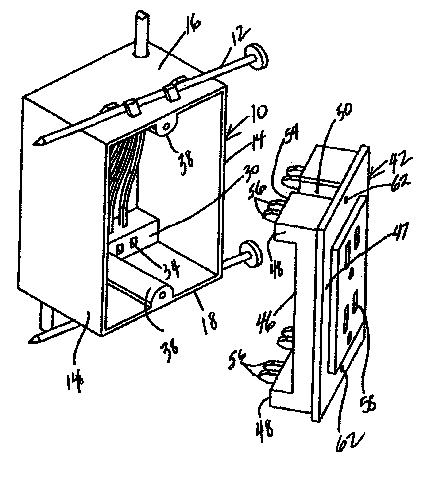
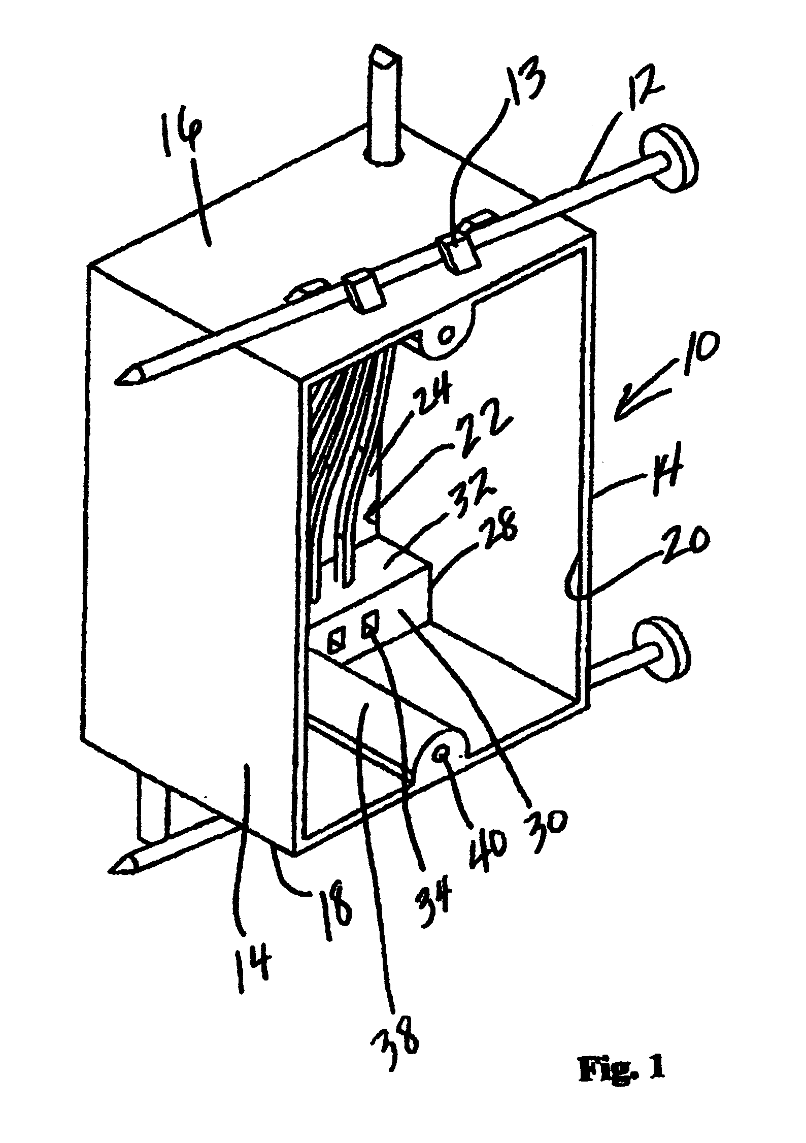
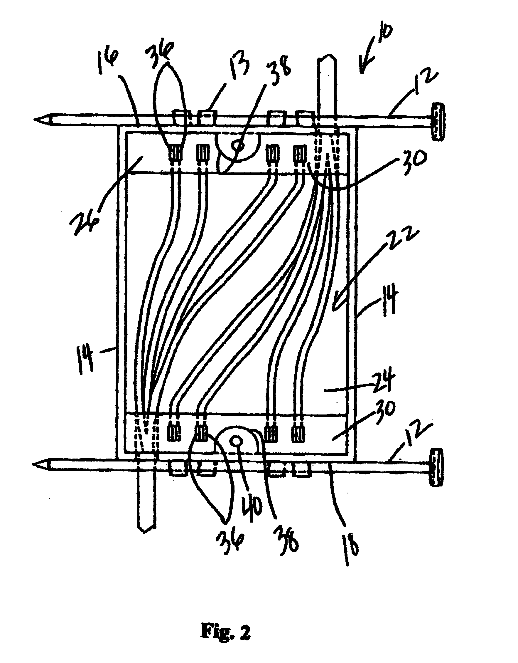
[0018]The present invention is directed to a modular plug-in electrical wiring system that includes a first or universal electrical modular unit for selective placement in a wall recess, and a second electrical modular unit for mating therewith. The system hereof is designed for ease of installation for any typical electrical components, such as receptacles, switches, and lighting fixtures. Different components, which by way of example may be receptacles and switches, when inserted or mated into the first modular unit, would automatically make necessary connections to electrical connectors that are built into the first modular unit at the time of manufacture. Likewise, light fixtures, ceiling fans, and smoke detectors, when installed, would also make the necessary connections to electrical connectors built into the ceiling box, for example, at the time of manufacture. This system, as will be apparent in the description which follows, will eliminate electrical boxes that are overstuf...


PUM


Abstract

A modular plug-in electrical wiring system that includes a pair of intermatable modular units that avoids the presence of a tangled mass of bare wires and wire nuts associated with conventional receptacle systems. A first unit is secured within a wall recess, such as between a pair of building studs, while the second unit slidable engages the first unit and may be removable secured thereto. The system is versatile as it can be used for mounting electrical appliances to a wall/ceiling.

Description

FIELD OF THE INVENTION[0001]This invention is directed to the field of hard wired electrical outlets, switches and the like, more particularly to a modular plug-in electrical wiring system for easy installation that avoids electrical outlet boxes having a tangled mass or exposed wires that can cause damage or injury.BACKGROUND OF THE INVENTION[0002]The present invention relates to a plug-in wiring system for use with residential and commercial construction, and for remodeling needs for hollow wall boxes. Typically, electrical wall outlets and switches can exhibit a tangled mess of electrical wires with plural exposed wires and bare terminals that can short and cause a fire, or even injury to people.[0003]The prior art has sought to rectify certain of these problems by providing a safer system to install and use. Exemplary prior art is reflected in the following U.S. Patents:[0004]a.) U.S. Pat. No. 6,156,971, to May, teaches an electrical system that includes modular components which...

Claims


Application Information

Patent Timeline
IPC IPC(8): H01R27/00H01R13/514H01R25/00H01R31/06
CPCH01R13/514H01R27/00H01R25/006H01R31/06
Inventor KIEFFER, JR., DON J.WILLIAMS, WALTER
Owner KIEFFER JR DON J
Why Eureka
Try Eureka