
Radiation conditioning system

a radiation conditioning and system technology, applied in the field of parallax display multi-view three-dimensional, can solve the problems of reducing image realism, problematic parallax display, and affecting the image quality of the image, so as to reduce the cost and complexity of fringe generation and greatly increase the system resolution

Inactive Publication Date: 2005-09-06
PARELLEL CONSULTING LIABILITY
View PDF15 Cites 47 Cited by
  • Summary
  • Abstract
  • Description
  • Claims
  • Application Information

AI Technical Summary

Benefits of technology

The system achieves high-resolution, high-brightness 3D imagery with smooth transitions between view zones, reducing the complexity and cost of fringe generation while closely approximating the light field of a 3D scene.

Problems solved by technology

In practice, parallax displays are problematic.
In general, there is significant noticeable light emitted in inappropriate directions, causing imagery from wrong viewpoints to be visible.
Furthermore, image realism is reduced because practical constraints limit the number of views that can be handled by each lens element.
Also, many known lenticular sheet parallax displays produce undesirable dark bands as the viewer transitions between viewpoints.
This has been a difficult obstacle.
It is computationally difficult to generate the AOM inputs that result in the desired light field.
Furthermore, the system uses components such as acousto-optic scanners and galvanometric scanners which are financially prohibitive.

Method used


Image

  • Radiation conditioning system
  • Radiation conditioning system
  • Radiation conditioning system

Examples


Embodiment Construction

[0054]Holographic video requires the generation of arbitrary three-dimensional (3D) light fields. A 3D light field can be generated by decomposing the field computationally into components—such as an ensemble of beams with various trajectories and profiles—and projecting these components by a projector whose light is modulated by a multi-region light-shaping element with time-varying properties.

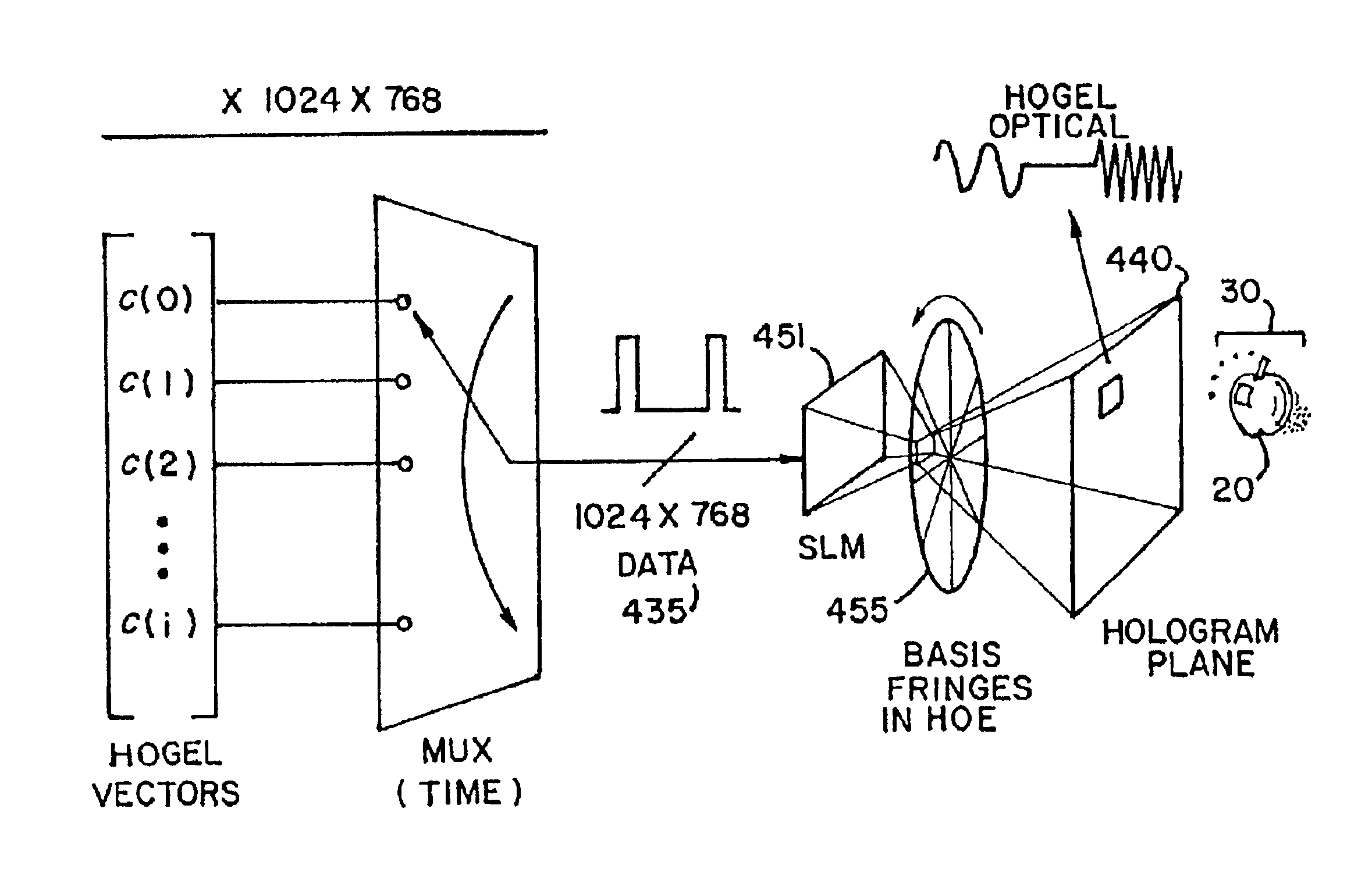
[0055]In FIG. 11, a 3D image 20 is generated in image volume 30 when the appropriate set of rays exit hologram plane 440. A diffractive optical element (DOE) 455, physically encoded with a diffraction pattern whose frequency is a sinusoidal function of angle, scans a time series of 2D bitmaps that exit a radiation projector 451 such as a spatial light modulator (SLM), an LED array or other device capable of projecting zero-, one-, two- or three-dimensional radiation. The SLM is controlled by a 3D data stream or control signal 435. The data stream 435 comprises a time division multiplexed set ...


PUM


Abstract

A holographic imaging system and method includes a radiation source for generating radiation. A data base has a set of elements, each element is indicative of a trajectory of a light ray exiting a point in a recorded scene. A spatial light modulator is receptive of the radiation from the radiation source and the elements of the data base mapped to the spatial light modulator, thereby projecting from the spatial light modulator an optical signal in the nature of a two dimensional bitmap of the recorded scene. A diffractive optical element includes a set of basis fringes receptive of the projected optical signal from the spatial light modulator for diffracting the optical signal in a specified direction. A multiplexer is receptive of the elements of the data base for multiplexing the elements of the data base to the spatial light modulator. A timing device synchronizes multiplexing the elements of the data base to the spatial light modulator and diffracting the optical signal in a specified direction.

Description

CROSS-REFERENCE TO RELATED APPLICATIONS[0001]This application claims the benefit of U.S. Provisional Patent Application Ser. No. 60 / 341,901, filed Dec. 19, 2001, which is incorporated herein by reference thereto as if set forth at length.[0002]This application claims the benefit of U.S. Provisional Patent Application Ser. No. 60 / 407,904, filed Sep. 3, 2002, which is incorporated herein by reference thereto as if set forth at length.BACKGROUND[0003]This disclosure relates generally to electronic display technology and more specifically to multi-view three-dimensional parallax displays.[0004]It is known that it is possible to create a three-dimensional image by approximating the wavefronts that emanate from three-dimensional (3-D) scenes. One such class of displays contains “parallax displays,” which project the appearance of a 3-D scene from multiple viewpoints. Parallax displays generally allow a viewer to move his head horizontally and / or vertically to inspect the 3-D scene from di...

Claims


Application Information

Patent Timeline
Patent Type & Authority Patents(United States)
IPC IPC(8): G02B26/10G02B27/22G03H1/22G02B5/32G02B30/27G03H1/26H04N13/00
CPCG02B26/106G02B27/2214G03H1/268H04N13/0402G02B5/32G03H2001/2292G03H2210/454G03H2225/31H04N13/302G02B30/27G03H1/04G02B27/10
Inventor FAVALORA, GREGG E.NAPOLI, JOSHUAOLIVER, DAVID-HENRY
Owner PARELLEL CONSULTING LIABILITY
Learn More