
Artificial disc prosthesis for replacing a damaged nucleus

a technology of artificial discs and prostheses, which is applied in the field of multi-chamber balloon implants, can solve the problems of putting pressure on the nerves affecting the healing effect of the spinal column, and limiting mobility, so as to reduce the invasiveness of the procedure and reduce the cost and complexity of the procedur

Active Publication Date: 2014-12-23
AFLATOON KAMRAN
View PDF8 Cites 1 Cited by
  • Summary
  • Abstract
  • Description
  • Claims
  • Application Information

AI Technical Summary

Benefits of technology

The implant effectively maintains intervertebral space, absorbs daily shocks, allows natural motion, resists hyperextension, and can be implanted minimally invasively, reducing surgical complexity and cost, while being easy to manufacture and assemble.

Problems solved by technology

Deterioration of an intervertebral disc can result from disease, trauma or aging, and results in symptoms including limited mobility, and severe pain.
This reduction may put pressure on the nerves of the spinal column causing pain.
Reduction in volume of the nucleus pulposus also reduces the disc's ability to absorb shock which, coupled with age or trauma related weakening of the annulus fibrosus often results in a disc herniation.
The bulge of a herniated disc may also put pressure on nearby nerve structures resulting in radiating pain, numbness, tingling, and diminished strength and / or range of motion.
In addition, the nucleus pulposus contains proteins which, if extruded from the disc into contact with the neural structures may also cause inflammation and significant pain.
In a significant number of patients surgical intervention is required when these non-invasive techniques are unsuccessful.
However, these surgical options are highly invasive and require prolonged hospitalization and recovery.
However, none of the preceding inventions presents an ideal replacement for the natural intervertebral disc is supplants.

Method used


Image

  • Artificial disc prosthesis for replacing a damaged nucleus
  • Artificial disc prosthesis for replacing a damaged nucleus
  • Artificial disc prosthesis for replacing a damaged nucleus

Examples


Embodiment Construction

[0052]The present invention comprises intervertebral disc implants incorporating single or multi-chamber balloons of varying shape that inflate to a unified whole of various forms including regular and irregular oblate spheroids and coiled strings of balloons, any of which may be implanted in an anterior, anterior-lateral, or a posterior surgical procedure with minimal incisions.

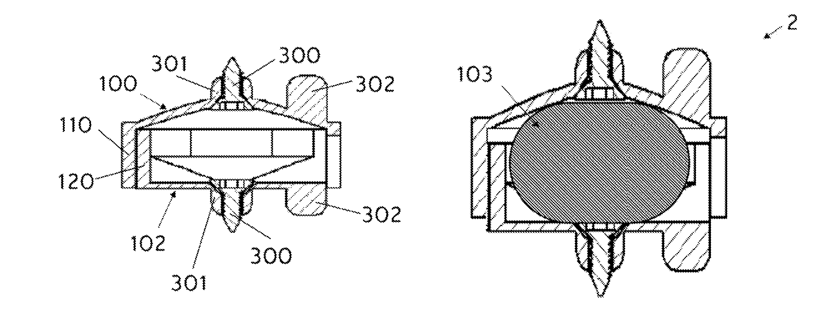
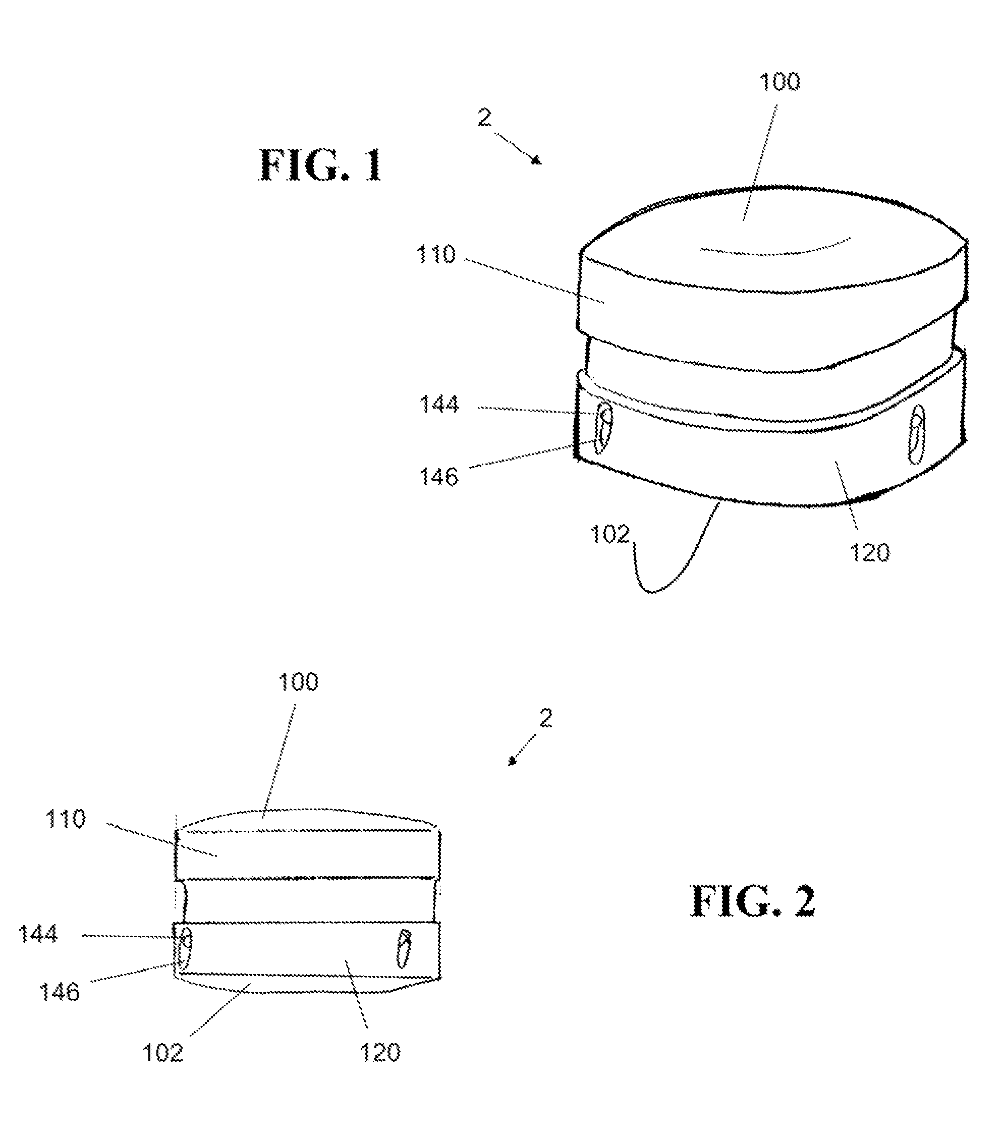
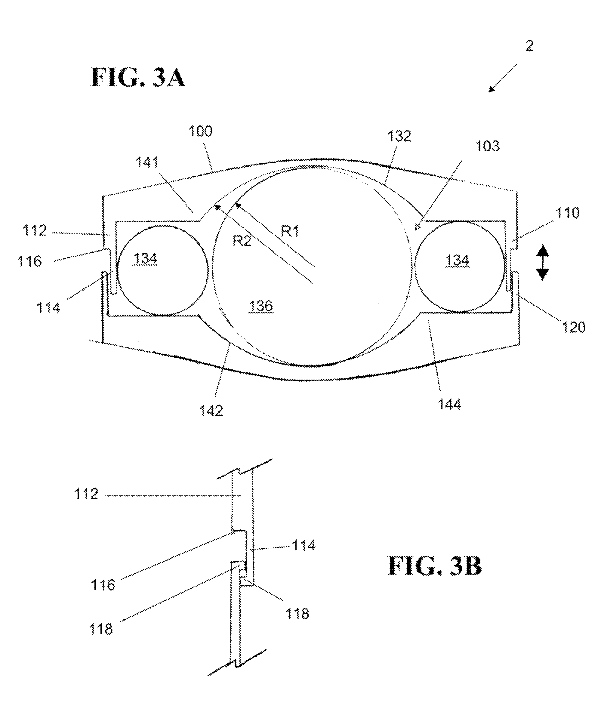
[0053]FIG. 1 is a perspective view of the intervertebral disc implant 2 according to a first embodiment of the present invention. FIG. 2 is a side view of the disc implant 2 of FIG. 1 and FIG. 3 is a cross sectional view of the disc implant 2 of FIG. 1. With combined reference to FIGS. 1, 2 and 3, a first embodiment of the present invention incorporates an upper, or superior, plate member 100, and a lower, or inferior, plate member 102, which are adapted to be secured to upper and lower vertebra, respectively, in a spinal column. A single or multi-component resilient member 103 (FIG. 3) is also provided, dis...


PUM

PropertyMeasurementUnit
resilientaaaaaaaaaa
shapeaaaaaaaaaa
spherical shapeaaaaaaaaaa

Abstract

A multi-piece disc replacement implant for replacing a disc removed by a discectomy including an upper plate member, a lower plate member, and an intermediate resilient member providing movement between the two plate members replicating the natural movement of the spine. The plate members are rigid and have orthogonal sidewalls forming an enclosure. The resilient member is an elastic solid or a multi-chamber balloon structure of fluid-filled sacks that collectively define a non-uniform shape such as an oblate spheroid, or a helically coiled string of beads. Such an implant is capable of supporting the compressive and cyclic loads required of a natural disc. The upper and lower plate members are cooperatively formed to selectively limit the allowable range of motion in any given direction and a provided with protrusions to be received in one or more channels cooperatively formed in the vertebrae and secured in place by a bone screw.

Description

CROSS-REFERENCE TO RELATED APPLICATIONS[0001]The present application is a continuation in part of U.S. patent application Ser. No. 12 / 384,095 filed Mar. 31, 2009 now U.S. Pat. No. 8,147,555 which is incorporated herein by reference and which claims priority from provisional application 61 / 072,480 filed on Mar. 31, 2008 which is also incorporated herein by reference.BACKGROUND OF THE INVENTION[0002]1. Field of the Invention[0003]The present invention relates to artificial intervertebral disc implants and, in particular, to a multi-chamber balloon implant that inflates to create an oblate spheroid shape.[0004]2. Description of the Background[0005]Intervertebral discs are oblate spherical structures (visibly flattened at the poles and bulging at the equator) that maintain the space between adjacent vertebrae and function as a cushion by absorbing and mitigating forces acting on the spine as a result of daily activities. Each intervertebral disc consists of an outer annulus fibrosus, wh...

Claims


Application Information

Patent Timeline
Patent Type & Authority Patents(United States)
IPC IPC(8): A61F2/30A61F2/44
CPCA61F2002/30579A61F2002/30884A61F2/442A61F2002/30224A61F2002/30586A61F2002/30584A61F2230/0091A61F2002/30601A61F2002/30261A61F2002/30014A61F2220/0025A61F2002/30563A61F2230/0069A61F2230/0065A61F2002/30578A61F2220/0033A61F2002/30372A61F2250/0018A61F2002/30291A61F2/441A61F2002/444A61F2002/302A61F2002/30528A61F2002/30841
Inventor AFLATOON, KAMRAN
Owner AFLATOON KAMRAN
Learn More