Vibration-damping shim for fan blade

a technology of vibration-damping shims and fan blades, which is applied in the field of fan blade vibration-damping shims, can solve the problems of premature wear and tear of the parts in contact, and achieve the effect of limiting the risk of premature wear and tear of the shim and limiting its wear and tear

Active Publication Date: 2014-12-16
SN DETUDE & DE CONSTR DE MOTEURS DAVIATION S N E C M A
View PDF13 Cites 14 Cited by
  • Summary
  • Abstract
  • Description
  • Claims
  • Application Information

AI Technical Summary

Benefits of technology

[0017]In addition, when contact occurs between the upstream ridge of the protruding zone and the disk, after the shim tips forward to a limited extent, this ridge has a low angle, limiting its wear and tear. Indeed, this low angle is synonymous with a substantial contact surface between the ridge and the disk, limiting the risks of premature wear and tear of the shim.
[0018]In addition, it is noted that the position of the protruding zone, at some distance from the upstream end of the upstream surface and upstream from the break in alignment, enables the shim not to become completely unbalanced, which means that its centre of gravity can be in the same area as in the damping shims of the prior art with a roughly flat upstream surface.

Problems solved by technology

The poor position held by shim 10 can lead to premature wear and tear and also such wear and tear of the parts in contact.

Method used


Image

  • Vibration-damping shim for fan blade
  • Vibration-damping shim for fan blade
  • Vibration-damping shim for fan blade

Examples


Embodiment Construction

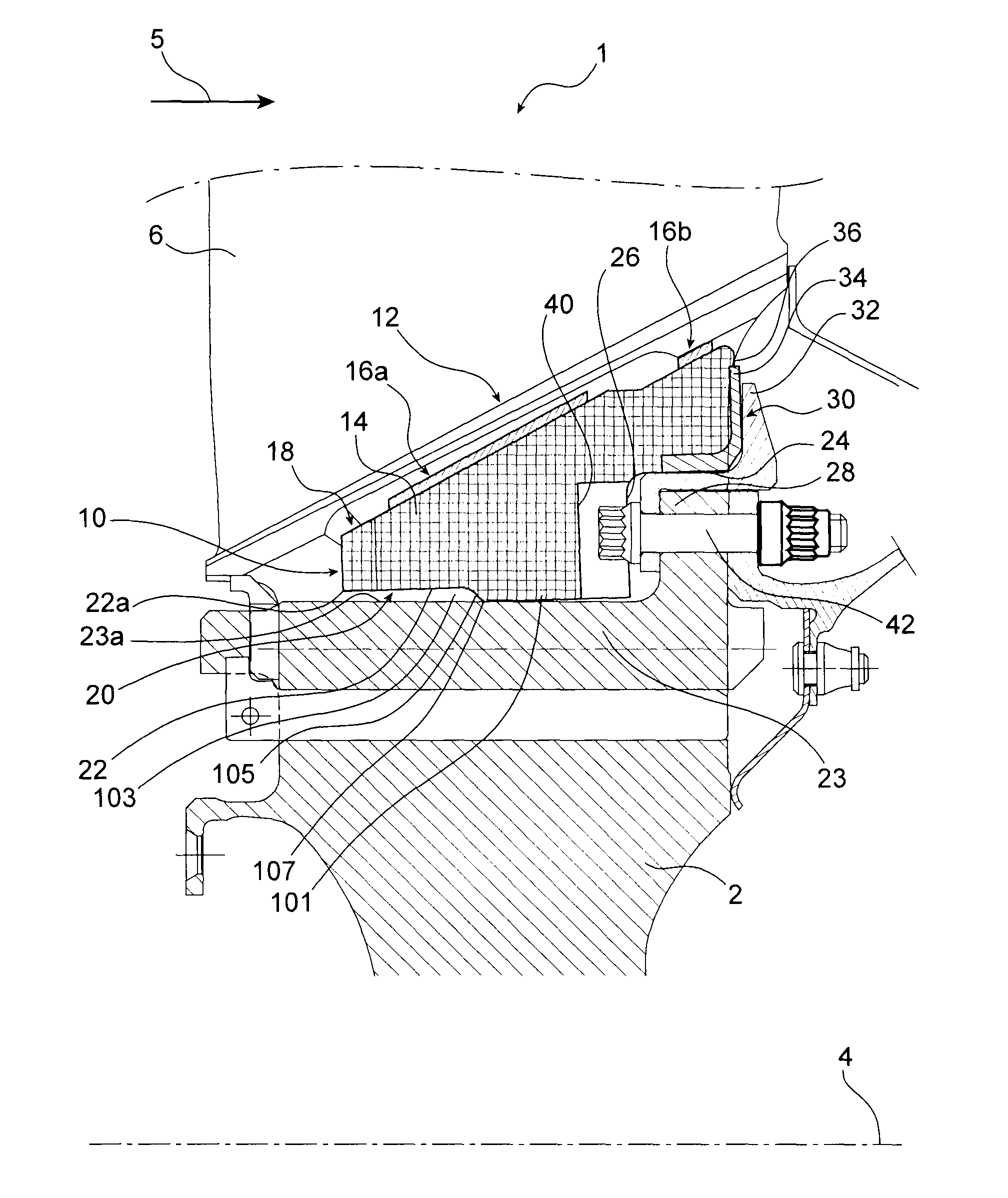
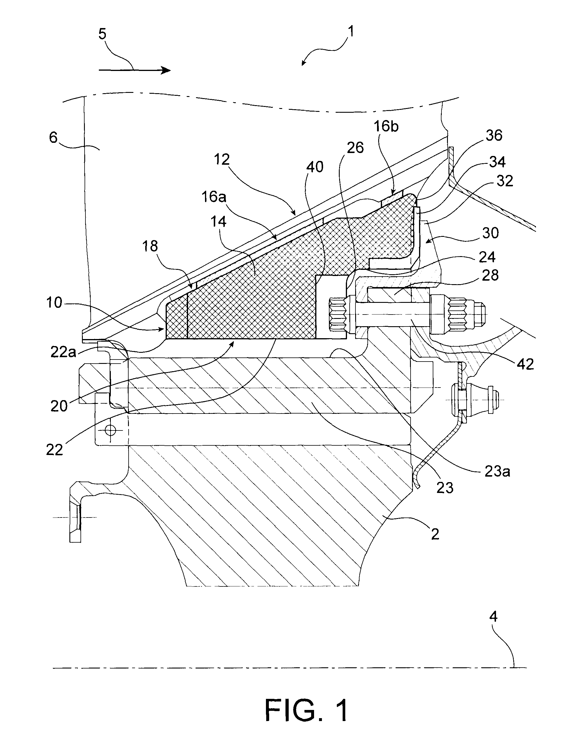
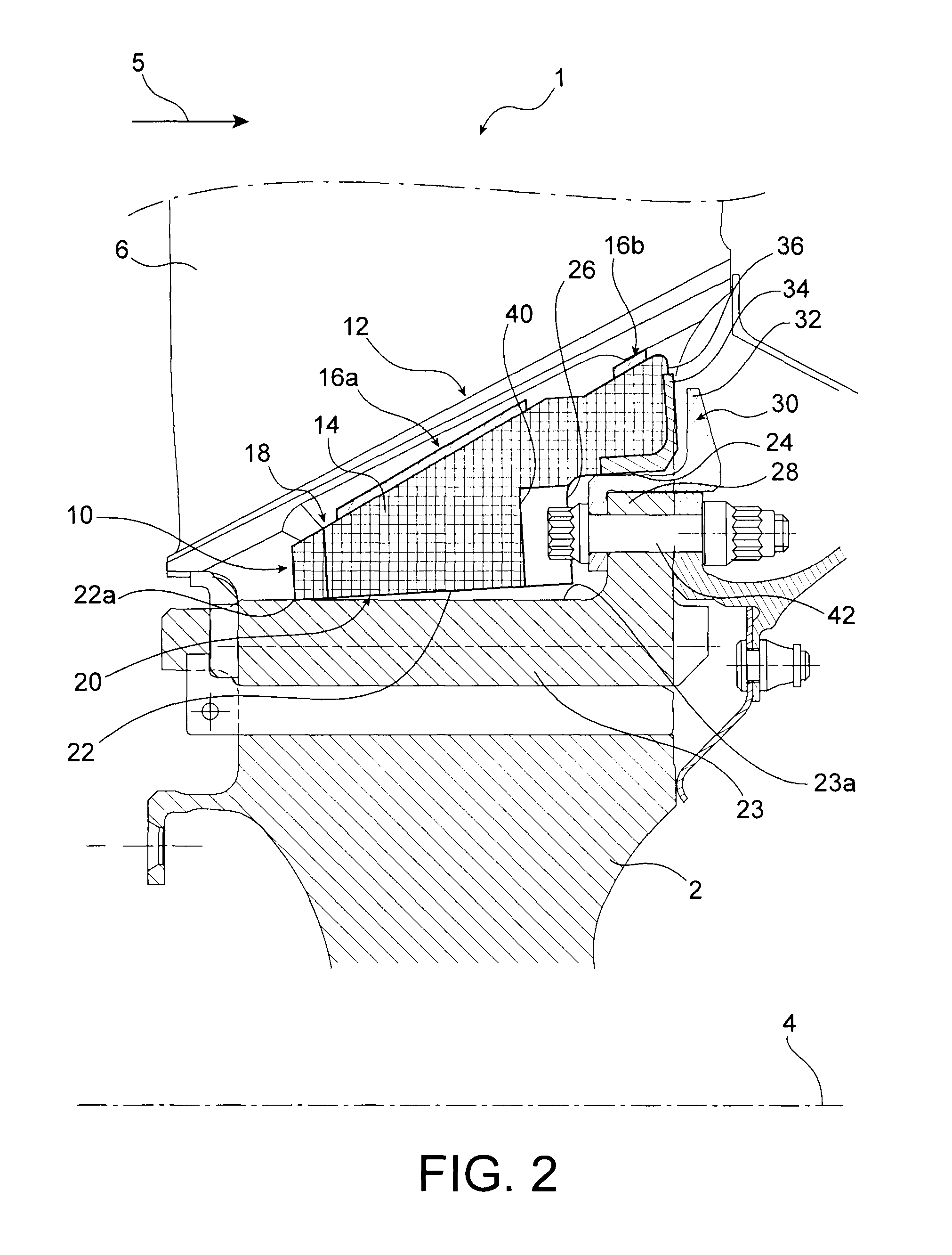
[0030]With reference to FIGS. 3 and 4, a fan 1 of an aircraft turbojet according to a preferred embodiment of the present invention can be seen. This fan differs from the one described with reference to FIGS. 1 and 2 only through the shape of upstream surface 22 of vibration-damping shim 10. Moreover, in the figures, the elements bearing the same numerical references are identical or similar elements.

[0031]Thus, upstream surface 22 positioned upstream from break in alignment 26 is no longer flat or slightly convex as in the prior art, but has a zone 101 protruding radially towards the interior, initiated at some distance from its upstream end 22a.

[0032]Consequently, upstream surface 22 of radially internal surface 20 starts by a recess 103 initiated from upstream end or ridge 22a, and then encounters a break in alignment 105 radially aligned towards the interior, which initiates protruding zone 101. The latter is extended downstream as far as break in alignment 26.

[0033]Recess 103 ...


PUM


Abstract

A vibration-damping shim configured to be interposed between a platform of a fan blade and a fan disk, including a radially external surface fitted with plates in contact with the fan blade platform, and a radially internal surface formed by an upstream surface, configured to be facing the disk, and a downstream surface separated from the upstream surface by a break in alignment. The upstream surface includes a zone protruding radially towards the interior, initiated at some distance from its upstream end.

Description

TECHNICAL FIELD[0001]The present invention relates generally to a fan for an aircraft turbomachine, preferably for a turbojet. More specifically, the invention concerns the vibration-damping shims interposed between the platform of the blades and the fan disk.STATE OF THE PRIOR ART[0002]A fan 1 for a turbojet known from the prior art is shown in FIG. 1. It presents a disk 2 centred on a longitudinal axis 4, which is the rotational axis of the fan. Fan blades 6 are assembled on the periphery of the disk in conventional fashion, and regularly distributed around axis 4.[0003]In addition, associated with each blade 6, vibration-damping shim 10 is interposed radially between platform 12 of the blade and the periphery of disk 2. Globally, this shim takes the form of an elastomer block 14 fitted with contact plates 16a, 16b designed to reduce the levels of vibration of the fan blades.[0004]More specifically, shim 10 has a radially external surface 18 fitted with two plates 16a, 16b in cont...

Claims


Application Information

Patent Timeline
Patent Type & Authority Patents(United States)
IPC IPC(8): F01D11/00F01D5/26F01D5/32F01D5/10F01D5/22F01D25/04F01D5/30
CPCY10S416/50F01D5/22F01D5/326F05D2260/30F05D2240/80F01D11/006F01D5/10F01D5/323F01D25/04F01D5/3053F01D5/26
Inventor BILZ, LAURENTMAROIS, FABRICEREGHEZZA, PATRICK JEAN-LOUISTRAN, JULIEN
Owner SN DETUDE & DE CONSTR DE MOTEURS DAVIATION S N E C M A
Why Eureka
Try Eureka