
Rotary bushing type crawler track

a crawler track and bushing technology, applied in the field of crawler tracks, can solve the problems of increasing running costs, applicable only to small-sized work machines, etc., and achieve the effect of reducing running costs

Inactive Publication Date: 2005-03-15
KOMATSU LTD
View PDF14 Cites 15 Cited by
  • Summary
  • Abstract
  • Description
  • Claims
  • Application Information

AI Technical Summary

Benefits of technology

In the present invention, the bushings (rotary bushings) engaging the driving wheel (sprocket) of the track type vehicle are rotatably disposed, thereby significantly restricting wear caused by a sliding contact occurring between the bushing and the driving wheel when the bushing engages and disengages the driving wheel and thereby alleviating a relative slip occurring when the bushing comes into engagement with the driving wheel. In addition, since a pair of links are coupled to each other by the beam and pin, each track link constituting the track chain has a rectangular framed construction, so that the track link has high rigidity, resulting in a durable crawler track. Accordingly, the invention provides a crawler track in which the service life of the bushings engaging the driving wheel of the track type vehicle can be improved, thereby reducing the running cost, and which is usable under high loading conditions such as unleveled lands and rocky areas and has a wide range of applications covering all types of work machines from small-sized to large-sized work machines.
In the invention, each beam is preferably press fit in its associated pair of links. With this arrangement, the beam is steadily joined to the pair of links so that the rigidity of the track link can be increased and disassembly of the track links becomes possible.

Problems solved by technology

Therefore, the track bushing 65 of the conventional crawler track 50 is rapidly worn out, resulting in increased running cost.
The crawler track disclosed in the above publication therefore presents the problem that it is applicable only to small-sized work machines which are used under low loading conditions such as flat lands and sandy areas.

Method used


Image

  • Rotary bushing type crawler track
  • Rotary bushing type crawler track
  • Rotary bushing type crawler track

Examples


Embodiment Construction

Referring now to the accompanying embodiment, a rotary bushing type crawler track will be concretely explained according to a preferred embodiment of the invention.

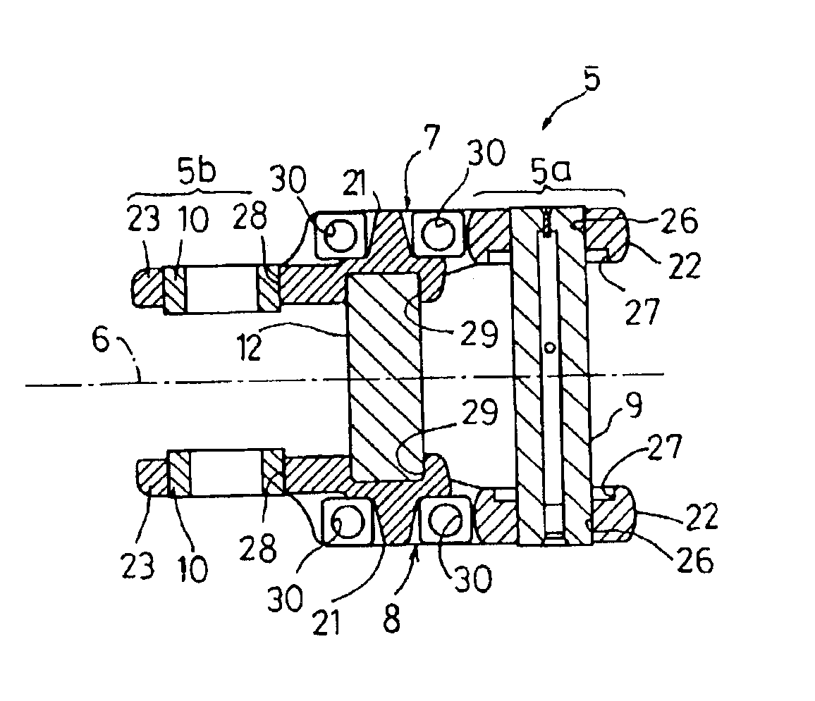
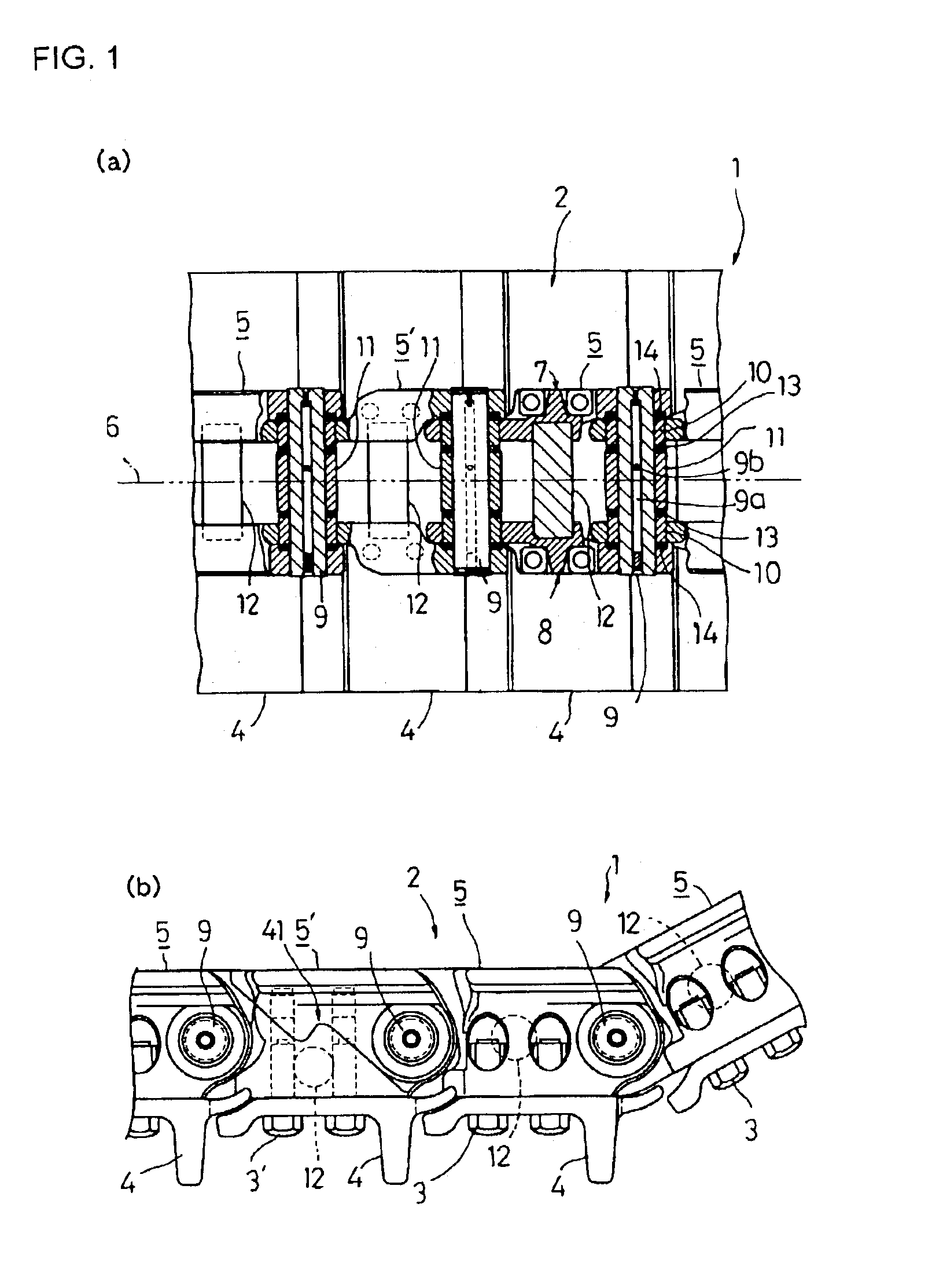
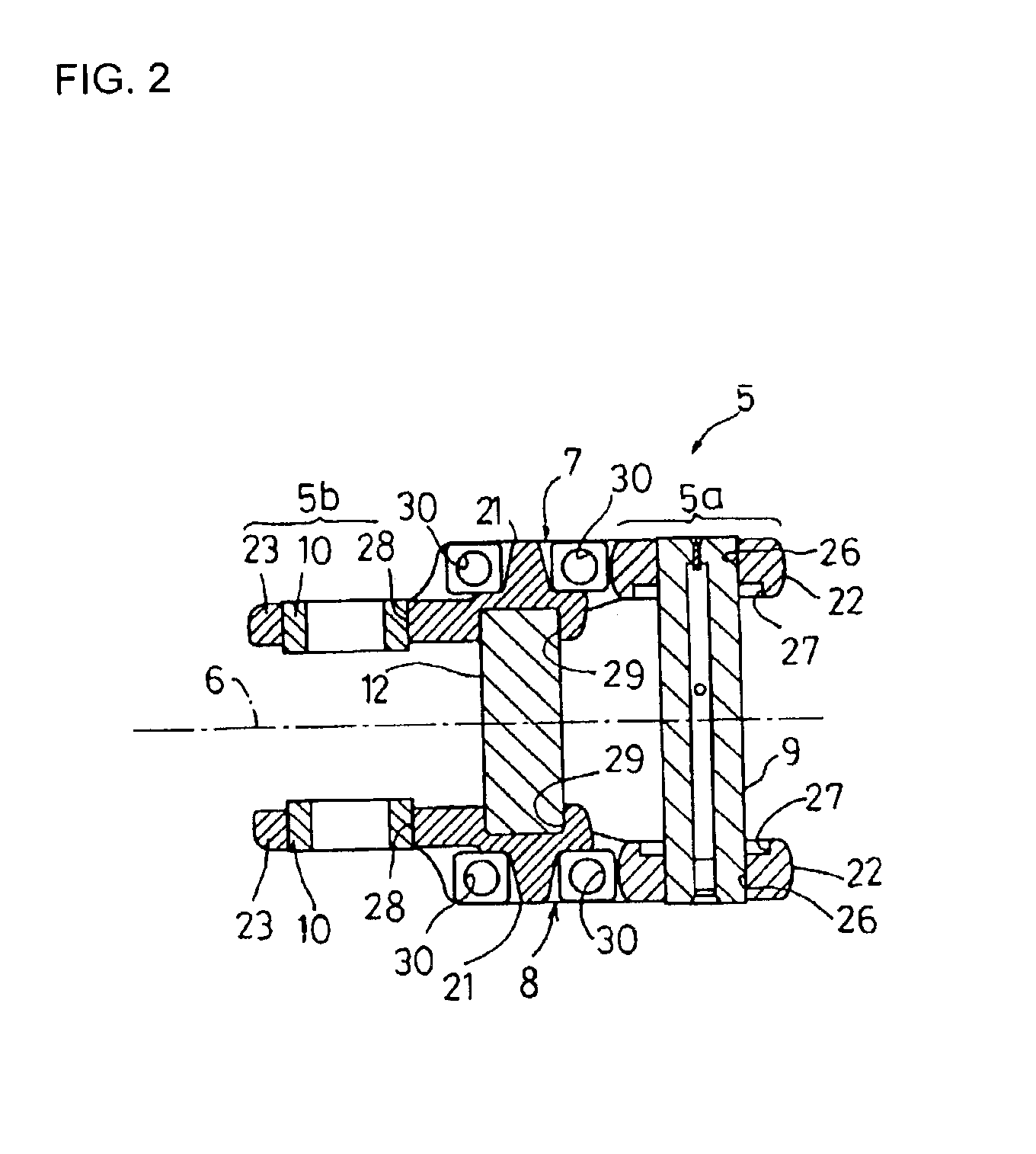
FIG. 1 is an explanatory structural view of a rotary bushing type crawler track according to one embodiment of the invention, wherein FIG. 1(a) is a sectional plan view of an essential part and FIG. 1(b) is a side view. FIG. 2 is an explanatory structural view of a track link according to the present embodiment. FIG. 3 is an entire perspective view of a right link constituting the track link.

The present embodiment is associated with one application in which the invention is applied to a bulldozer (not shown) that is a kind of track type vehicle. The bulldozer according to the present embodiment comprises a vehicle body (not shown); and rotary bushing type crawler tracks 1 disposed at both sides of the vehicle body, for forwardly and backwardly moving and turning the vehicle body.

Each rotary bushing type crawler track 1 co...


PUM


Abstract

A crawler track is provided which is improved in the service life of bushings engaging a driving wheel (sprocket) of a track type vehicle, thereby reducing the running cost and which can be used under high loading conditions and therefore has a wide range of applications covering all types of machines from small-sized to large-sized work machines. In the crawler track of the track type vehicle having a track chain composed of a plurality of track links each having a pair of links spaced apart from each other in a lateral direction and a pin for coupling the pair of links, the track links being connected in the form of a loop by their pins, each bushing engaging the driving wheel (sprocket) is rotatably mounted to its associated pin and a beam for coupling the pair of links is disposed at the center of the space between every adjacent pins.

Description

TECHNICAL FIELDThe present invention relates to a crawler track for use in track type vehicles and more particularly to a rotary bushing type crawler track in which bushings engaging a driving wheel of a track type vehicle are rotatable.BACKGROUND ARTReferring to FIG. 6(a), it can be seen that a known crawler track 50 mounted on a bulldozer (not shown) that is a kind of track type vehicle comprises a track chain 51 wound around an idler (not shown) that is a coupled driving wheel and around a sprocket (not shown) that is a driving wheel; and track shoes 52 attached to the track chain 51. The track chain 51 is composed of a plurality of track links 53 which are connected in the form of a loop, each track link 53 comprising a pair of links 61 spaced apart from each other in a widthwise (lateral) direction of the crawler track; a pin 63 for coupling the pair of links 61 at their first ends 62; and a track bushing 65 for coupling the pair of links 61 at their second ends 64. In each tra...

Claims


Application Information

Patent Timeline
Patent Type & Authority Patents(United States)
IPC IPC(8): B62D55/20B62D55/21B62D55/205
CPCB62D55/211
Inventor YAMAMOTO, TEIJI
Owner KOMATSU LTD
Learn More