Belt drive device and image forming apparatus

a drive device and drive device technology, applied in the direction of electrographic process, instruments, transportation and packaging, etc., can solve the problems of endless belt skewing, increased friction between the bead and the pulley, and wear of the bead, so as to prevent the skewing of the endless belt and restrict the wearing of the bead

Active Publication Date: 2011-04-12
OKI ELECTRIC IND CO LTD
View PDF14 Cites 15 Cited by
  • Summary
  • Abstract
  • Description
  • Claims
  • Application Information

AI Technical Summary

Benefits of technology

[0006]An object of the present invention is to provide a belt drive device and an image forming apparatus capable of preventing the skewing of an endless belt to thereby prevent the wearing of a component (for example, a bead), so as to prevent the endless belt from being dropped out of the pulley.
[0008]With such an arrangement, it becomes possible to prevent the skewing of the endless belt. In a configuration in which a bead on the inner circumference of the endless belt engages a groove of a pulley, the wearing of the bead can be restricted. Therefore, it becomes possible to prevent the bead from moving out of the groove of the pulley, and to prevent the endless belt from being dropped out of the pulley.

Problems solved by technology

However, there is a possibility that a skewing of the endless belt may occur, depending on a parallelism between the two rollers, an imbalance of tension applied to the endless belt, a dimensional accuracy of the rollers, or the like.
However, since the conventional belt drive device prevents the skewing of the endless belt by means of the engagement between the bead and the groove of the pulley, the friction between the bead and the pulley may increase when the force of the skewing increases.
In such a case, the bead may be worn, and the worn bead may move out of the groove of the pulley, with the result that the endless belt may be dropped out of the pulley.
Once the endless belt is dropped out of the pulley, the belt drive device does not recover its original condition by itself, and therefore an expensive replacement of belt drive device is inevitable.

Method used


Image

  • Belt drive device and image forming apparatus
  • Belt drive device and image forming apparatus
  • Belt drive device and image forming apparatus

Examples


first embodiment

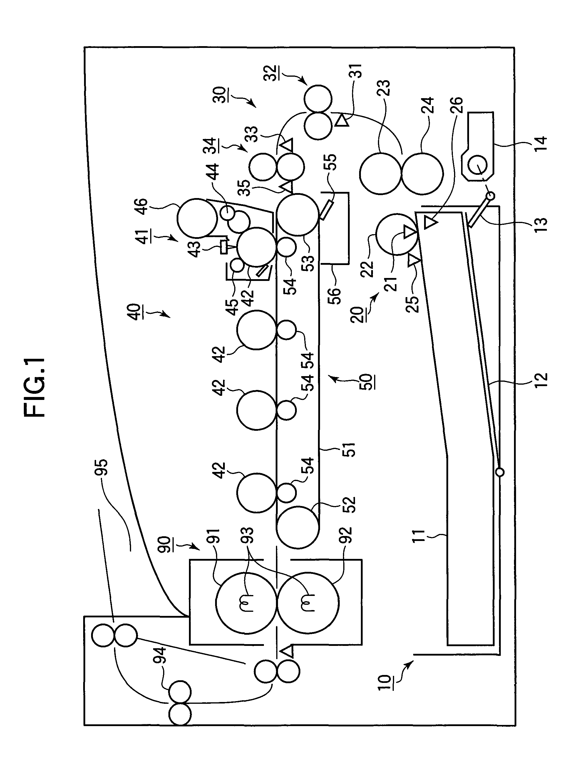
[0042]FIG. 1 is a schematic view of an image forming apparatus according to the first embodiment of the present invention.

[0043]As shown in FIG. 1, a sheet tray 10 is detachably attached to the image forming apparatus. Sheets 11 (i.e., recording media) are stacked in the sheet tray 10. In the sheet tray 10, a sheet stacker plate 12 is rotatably supported by a not shown support shaft, and the sheets 11 are stacked on the sheet stacker plate 12. Guide members (not shown) are provided in the sheet tray 10 for defining the stacking position of the sheets 11. The guide members determine the stacking position of the sheets 11 in the lateral direction perpendicular to the feeding direction of the sheets 11, and the stacking position of the sheets 11 in the feeding direction of the sheets 11 (i.e., to the right in FIG. 1).

[0044]A lift-up lever 13 is disposed at an exit side of the sheet tray 10, and is rotatably supported by a not shown support shaft. The support shaft is disconnectably con...

second embodiment

[0078]Next, the second embodiment of the present invention will be described. The components that are the same as those of the first embodiment are assigned the same reference numerals, and duplicate description is omitted. Further, regarding the operation and the effect that are the same as those of the first embodiment, duplicate description is omitted.

[0079]FIGS. 14, 15 and 16 are sectional views showing first, second and third states of the operation of the belt drive device according to the second embodiment of the present invention.

[0080]In the second embodiment, the bead 58 (fixed to the transfer belt 51 in the first embodiment) is not provided. Further, a pulley 71 of the second embodiment has no groove which engages the bead 58, but has a flange portion 71a which contacts the lateral end of the transfer belt 51.

[0081]The operation of the belt drive device according to the second embodiment will be described.

[0082]As shown in FIG. 14, when the transfer belt 51 shifts to the ...

third embodiment

[0090]Next, the third embodiment of the present invention will be described. The components that are the same as those of the first and second embodiments are assigned the same reference numerals, and duplicate description is omitted. Further, regarding the operation and effect that are the same as those of the first and second embodiments, duplicate description is omitted.

[0091]FIGS. 17, 18 and 19 are sectional views showing first, second and third states of the operation of the belt drive device according to the third embodiment of the present invention.

[0092]In the third embodiment, the pulley 57 and the pulley 71 (as in the first and second embodiments) are not provided. Further, a roller tilting lever 73 of the third embodiment has a flange portion 73b that contacts the lateral end of the transfer belt 51. The roller tilting lever 73 has a rotation axis 73a tilted with respect to the rotation axis O1 of the drive roller 52 (FIG. 6).

[0093]The operation of the belt drive device a...


PUM

PropertyMeasurementUnit
circumferenceaaaaaaaaaa
movementaaaaaaaaaa
angleaaaaaaaaaa

Abstract

A belt drive device includes a plurality of rollers and an endless belt stretched around the rollers, and configured to drive the endless belt by rotating the rollers. The belt drive device further includes a roller-shaft shifting member that shifts at least one end of a shaft of at least one roller of the above described rollers in accordance with the movement of the endless belt in the axial direction of the roller.

Description

BACKGROUND OF THE INVENTION[0001]This invention relates to a belt drive device and an image forming apparatus having the belt drive device.[0002]A conventional electrophotographic image forming apparatus uses an endless belt for feeding a recording media to an image forming portion in which an image is formed on the recording media. Such an image forming apparatus includes a belt drive device having the endless belt adjacent to the image forming portion. The belt drive device feeds the recording media to the image forming portion by moving the endless belt that absorbs the recording media, so that the image is formed on the recording media in the image forming portion.[0003]The belt drive device includes two rollers (provided in parallel to each other) around which the endless belt is stretched, and drives at least one of the two rollers to thereby move the endless belt. However, there is a possibility that a skewing of the endless belt may occur, depending on a parallelism between ...

Claims


Application Information

Patent Timeline
Patent Type & Authority Patents(United States)
IPC IPC(8): B65H5/02B65G39/16
CPCB41J11/007B65G39/16B65H5/021G03G15/0194G03G15/1625B65H2404/252B65H2301/331
Inventor KITAMURA, MAKOTO
Owner OKI ELECTRIC IND CO LTD
Why Eureka
Try Eureka