Head stack load comb for controlled head loading

a load comb and head technology, applied in the direction of mounting the head within the housing, manufacturing tools, instruments, etc., can solve the problems of affecting the load comb's load velocity, the head and disk may change the slope of the load comb ramp, and the head and disk damage risk is increased

Inactive Publication Date: 2005-09-13
WESTERN DIGITAL TECH INC
View PDF5 Cites 62 Cited by
  • Summary
  • Abstract
  • Description
  • Claims
  • Application Information

AI Technical Summary

Benefits of technology

[0011]The present invention relates to a head stack load comb for use in the assembly of a disk drive and a method of ass...

Problems solved by technology

Head disk interactions, such as head slaps, may increase the risk of head and disk damage.
Unfortunately, head disk interactions, such as head slaps, still occur and with time, and after many uses, the slope of the ramps of the load comb may change such that they may fail to adequately control the load velocity of the heads onto the disks properly.
Th...

Method used


Image

  • Head stack load comb for controlled head loading
  • Head stack load comb for controlled head loading
  • Head stack load comb for controlled head loading

Examples


Embodiment Construction

[0028]The present invention relates to a load comb and a method for using the load comb in the assembly of a disk drive, and particularly, to the use of the load comb in a head-disk merge operation during the assembly of a disk drive.

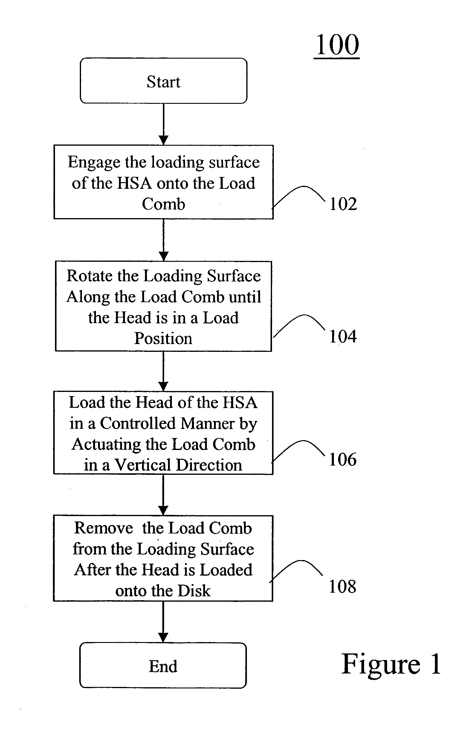
[0029]With reference to FIG. 1, FIG. 1 shows a method 100 for the controlled loading of a head of a head stack assembly (HSA) onto a disk during the assembly of a disk drive, according to one embodiment of the invention. Particularly, the method 100 is used during a head-disk merge operation. It should be appreciated that a HSA, as is known in the art, includes an actuator arm, a head, and a loading surface.

[0030]According to the method 100, at step 102, the loading surface of the HSA is engaged onto the load comb. Next, at step 104, the loading surface of the HSA is rotated along the load comb until the head is in a load position. At step 106, the head of the HSA is loaded onto the disk in a controlled manner. Loading the head in a controlled manner in...


PUM

PropertyMeasurementUnit
Diameteraaaaaaaaaa
Currentaaaaaaaaaa

Abstract

Disclosed is a head stack load comb used in the controlled loading of a head of a head stack assembly (HSA) onto a disk during the assembly of a disk drive. The HSA includes an actuator arm, a head, and a loading surface. The load comb includes a base structure and at least one ramp finger projecting approximately perpendicularly from the base structure. In order to load the head in a controlled manner onto the disk, the loading surface of the HSA is rotated along the ramp finger until the head is in a load position and then the base structure is actuated in a vertical direction such that the ramp finger is correspondingly actuated in the vertical direction towards the disk until the head is loaded onto the disk.

Description

BACKGROUND OF THE INVENTION[0001]1. Field of the Invention[0002]The present invention relates to disk drives. More particularly, the present invention relates to a head stack load comb for use in the assembly of a disk drive and a method of assembling a disk drive utilizing the head stack load comb, in which the head stack load comb provides for controlled head loading.[0003]2. Description of the Prior Art and Related Information[0004]A huge market exists for hard disk drives for mass-market host computer systems such as servers, desktop computers, and laptop computers. To be competitive in this market, a hard disk drive should be relatively inexpensive, and should accordingly embody a design that is adapted for low-cost mass production. Further, there exists substantial competitive pressure to continually develop hard disk drives that have increasingly higher storage capacity, that provide for faster access to data, and at the same time conform to decreasingly smaller exterior size...

Claims


Application Information

Patent Timeline
IPC IPC(8): G11B5/127H04R31/00
CPCG11B5/105G11B5/54Y10T29/53165Y10T29/49025Y10T29/49028Y10T29/49027
Inventor SUBRAHMANYAM, JAI N.HAUERT, SERGE
Owner WESTERN DIGITAL TECH INC
Why Eureka
Try Eureka