Bicycle component operating device

a technology of operating device and bicycle, which is applied in the direction of steering device, pedal equipment, pedals, etc., can solve the problems of preventing efficient power transfer, affecting and the discomfort of the handlebar, so as to improve the aerodynamic characteristics of the bicycl

Inactive Publication Date: 2005-09-13
SHIMANO INC
View PDF12 Cites 24 Cited by
  • Summary
  • Abstract
  • Description
  • Claims
  • Application Information

AI Technical Summary

Benefits of technology

[0009]One object of the present invention is to provide a bicycle handle bar, which contributes to improved aerodynamic characteristics for the cyclist.

Problems solved by technology

These prior handlebars are sometimes uncomfortable, prevent efficient power transfer to the drivetrain of the bicycle, and contribute to increased air drag forces.
However, it can be difficult for the rider to control brake operating devices, derailleur operating devices and cycle-computers (optionally) when using these attachments or additional bars.
Additionally, these attachments can be cumbersome, difficult to install and relatively heavy.
Moreover, these attachments do not always allow efficient power transfer from the rider to the drive train of the bicycle.
Furthermore, these attachments do not always minimize air drag forces and can be uncomfortable for the rider.

Method used


Image

  • Bicycle component operating device
  • Bicycle component operating device
  • Bicycle component operating device

Examples


second embodiment

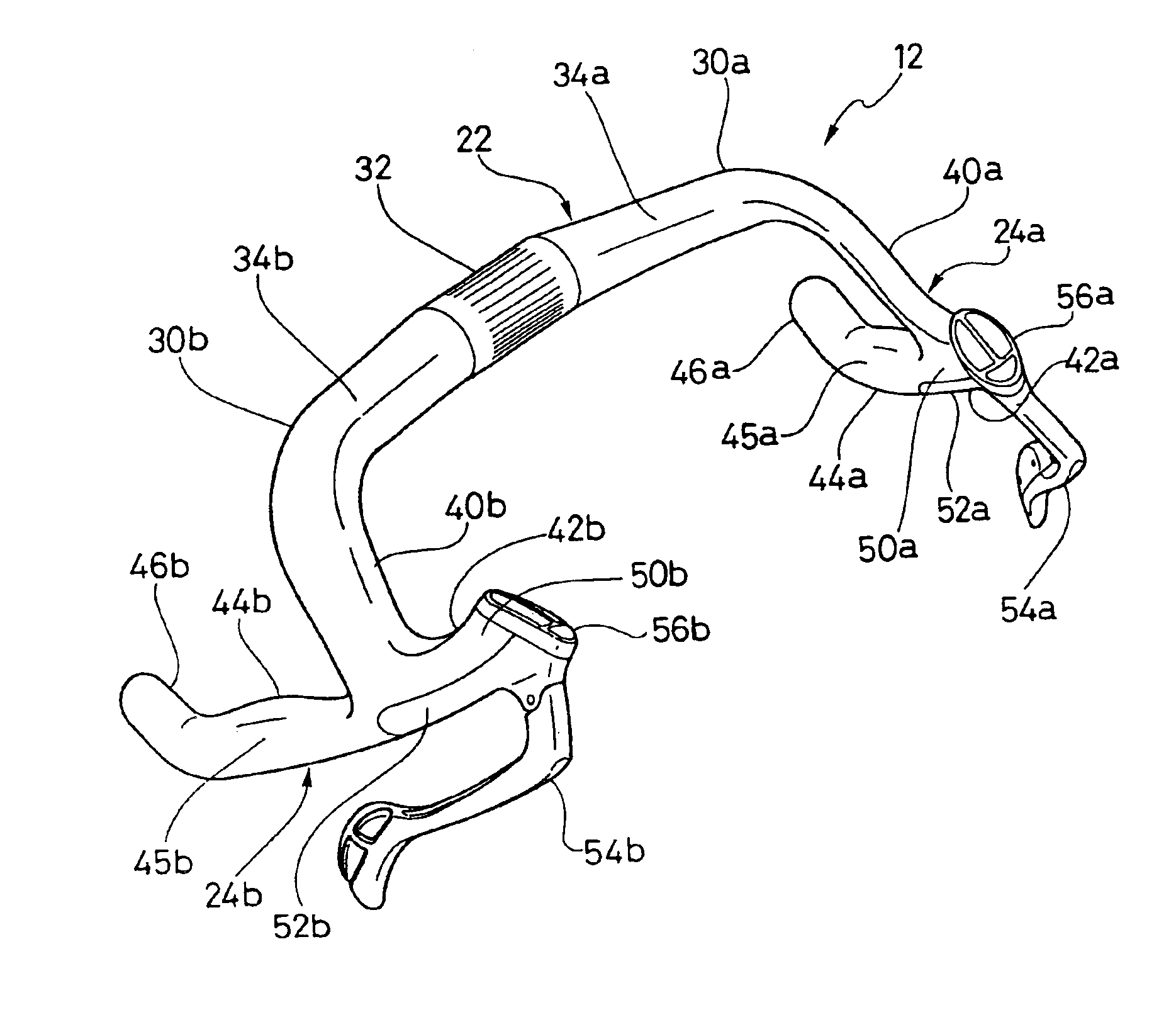
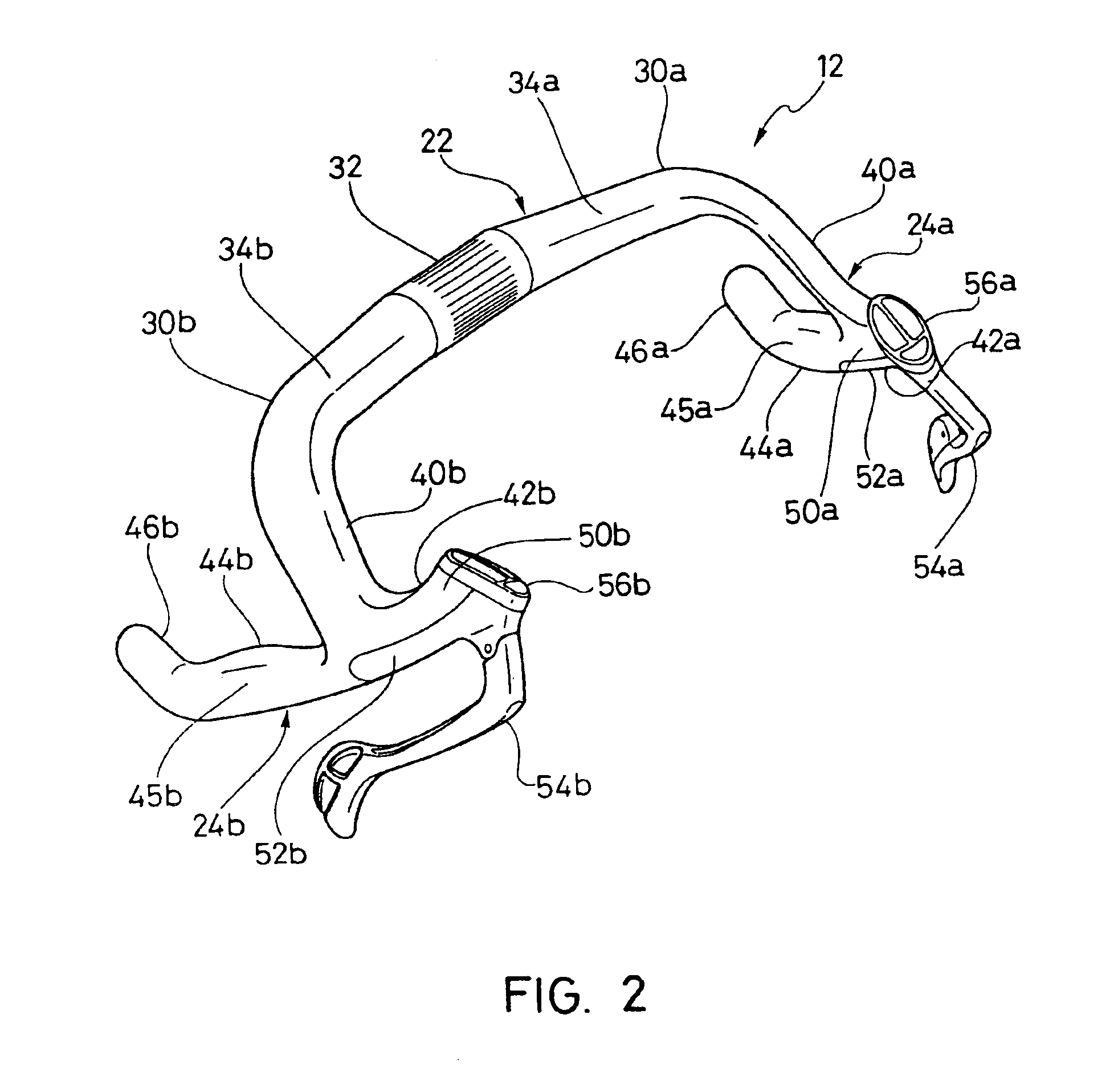
[0062]Referring now to FIGS. 13 and 14, an alternate handlebar 112 is illustrated in accordance with a second embodiment of the present invention. Basically, handlebar 112 is identical to handlebar 12 of the first embodiment, except that outer gripping portions 124a and 124b are modified versions of outer gripping portions 24a and 24b of the first embodiment. More specifically, handlebar 112 utilizes alternate connections between a mounting sections 150a and 150b, and bracket sections 152a and 152b, respectively. In view of the similarities between handlebar 112 and 12, the following description of handlebar 112 will focus mainly on the differences. However, it will be apparent to those skilled in the art from this disclosure that most of the description of handlebar 12 applies to the description of handlebar 112.

[0063]Handlebar 112 basically includes a transverse portion 122 and a pair of outer gripping portions 124a and 124b (first and second). Transverse portion 122 is preferably...


PUM


Abstract

An outer gripping portion of a bicycle handlebar includes a mounting section and a bracket section. The mounting section has a first cross-sectional shape. The bracket section has a second cross-sectional shape and is releasably coupled to the mounting section to form a first gripping section. The first and second cross-sectional shapes of the mounting section and the bracket section have flush longitudinal edges that mate together to form a first annular gripping surface of the first gripping section. Preferably, the bicycle handlebar includes a pair of outer gripping portions coupled to opposite ends of a transverse portion.

Description

CROSS-REFERENCE TO RELATED APPLICATIONS[0001]This application is a divisional application of U.S. patent application Ser. No. 09 / 818,541, filed on Mar. 28, 2001, now U.S. Pat. No. 6,546,827. The entire disclosure of U.S. patent application Ser. No. 09 / 818,541 is hereby incorporated herein by reference.BACKGROUND OF THE INVENTION[0002]1. Field of the Invention[0003]This invention generally relates to a bicycle handlebar. More specifically, the present invention relates an aerodynamic bicycle handlebar with a gripping section formed by a mounting section and a bracket section mounted flush with the mounting section to form a continuous annular gripping surface.[0004]2. Background Information[0005]Bicycling is becoming an increasingly more popular form of recreation as well as a means of transportation. Moreover, bicycling has also become a very popular competitive sport for both amateurs and professionals. Whether the bicycle is used for recreation, transportation or competition, the ...

Claims


Application Information

Patent Timeline
Patent Type & Authority Patents(United States)
IPC IPC(8): B62K21/00B62K21/12B62K21/26B62K23/06
CPCB62K21/12Y10T74/2078Y10T74/20828Y10T74/20287
Inventor IRIE, YOSHINORI
Owner SHIMANO INC
Why Eureka
Try Eureka