Robotic cylinder welding

a robotic cylinder and welding technology, applied in the direction of soldering equipment, manufacturing tools, auxillary welding devices, etc., can solve the problems of defective welding, inability to alter the welding process in an open-loop system, and inability to provide existing open-loop welding systems

Inactive Publication Date: 2005-09-13
LINCOLN GLOBAL INC
View PDF19 Cites 40 Cited by
  • Summary
  • Abstract
  • Description
  • Claims
  • Application Information

AI Technical Summary

Benefits of technology

[0011]A first embodiment of the present application is directed to a method and system used to weld a cylindrical workpiece. A substantially cylindrical workpiece is loaded into a workpiece support, and a robotic welding arm is positioned located at a start position. A value representing a size of the cylindrical workpiece is input into a robot controller via a system interface. Inputting of the size value to the robotic interface obtains a control program. Operation of the obtained control program is initiated by an operator, causing the robot arm to move a preprogrammed distance toward a work surface of the workpiece. Then a welding process is performed by the welder carried on the robot arm in accordance with the control program. The process includes initiating operation of the welder, and moving the welder in a pattern appropriate for the welding operation. The workpiece and welder are moved relative to each other so as to perform the welding process as determined by the control program.

Problems solved by technology

The inability to alter the welding process in an open-loop system has in certain situations been considered a drawback.
Attempting to weld a workpiece using a control program created for a different sized workpiece will result in defective welding due to misplacement of the welder.
Thus, existing open-loop welding systems do not provide, economical process to weld a number of differently sized cylindrical workpieces, where such a system is able to economically weld part-volumes as small as a single part.
On the other hand, while robotic systems having a closed-loop design permit for alterations to the welding process dependent upon existing conditions, the inclusion of these feedback systems greatly complicate and increase the cost of the welding systems.
For example, a laser vision system incorporated with the robotic arm, may cost as much as the robotic system itself.
Thus, the cost of adding feedback controls to alter a welding procedure creates economic inefficiencies when attempting to weld small numbers of workpieces.
The economic benefit of automating the welding process is therefore offset by the high cost of incorporating the components needed for a closed-loop system.
A further drawback of existing robotic systems, is their failure to address the ability to weld two cylindrical workpieces not completely in the same horizontal plane.
However, existing systems apparently only address the welding of two cylindrical workpiece portions which are in the same horizontal plane.
Another drawback in existing robotic systems, is the inability to provide for operator interaction during the welding process, which permits for refined operator control of the location of the welder, even while the welding control program is functioning.

Method used


Image

  • Robotic cylinder welding
  • Robotic cylinder welding
  • Robotic cylinder welding

Examples


Embodiment Construction

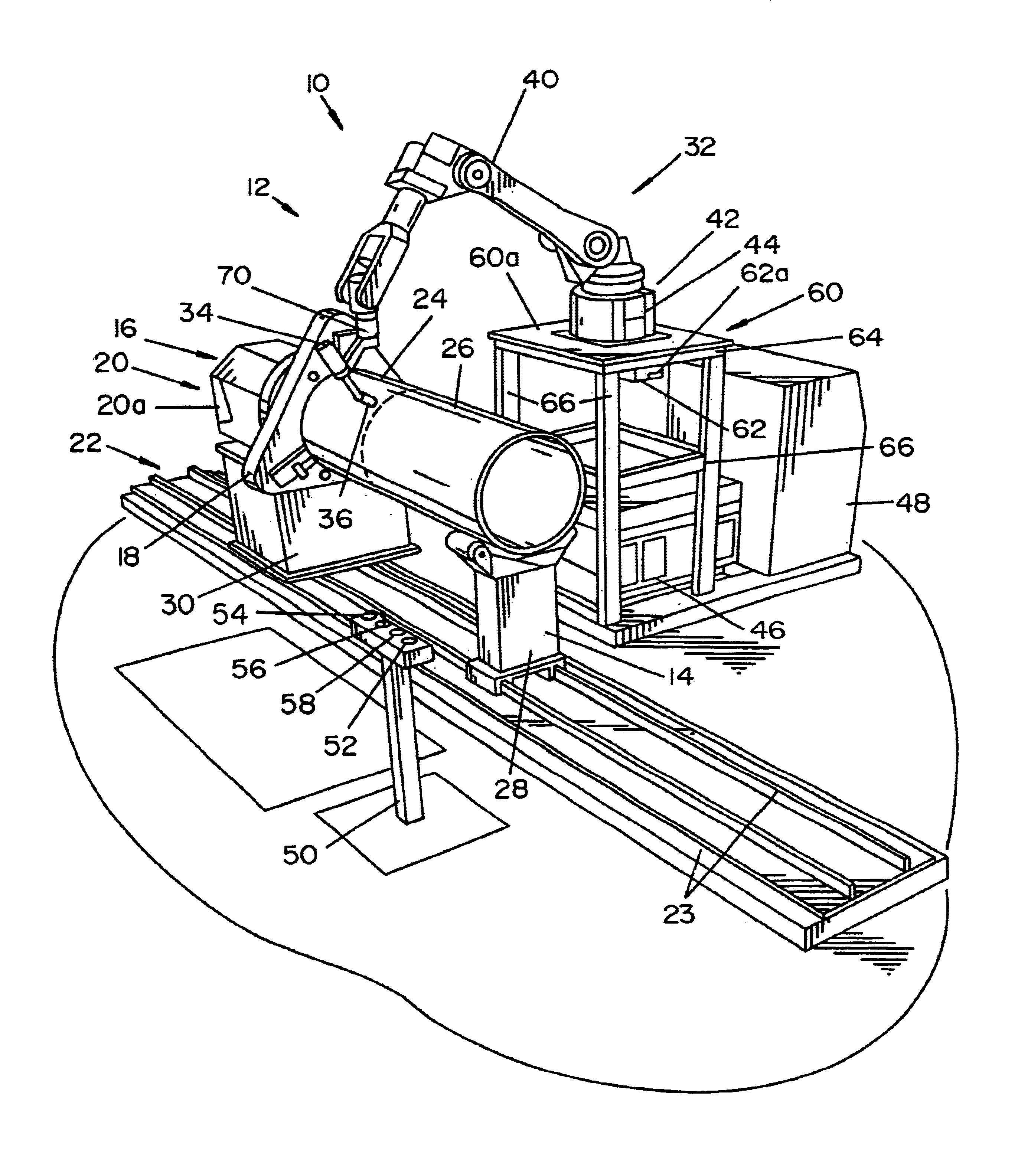
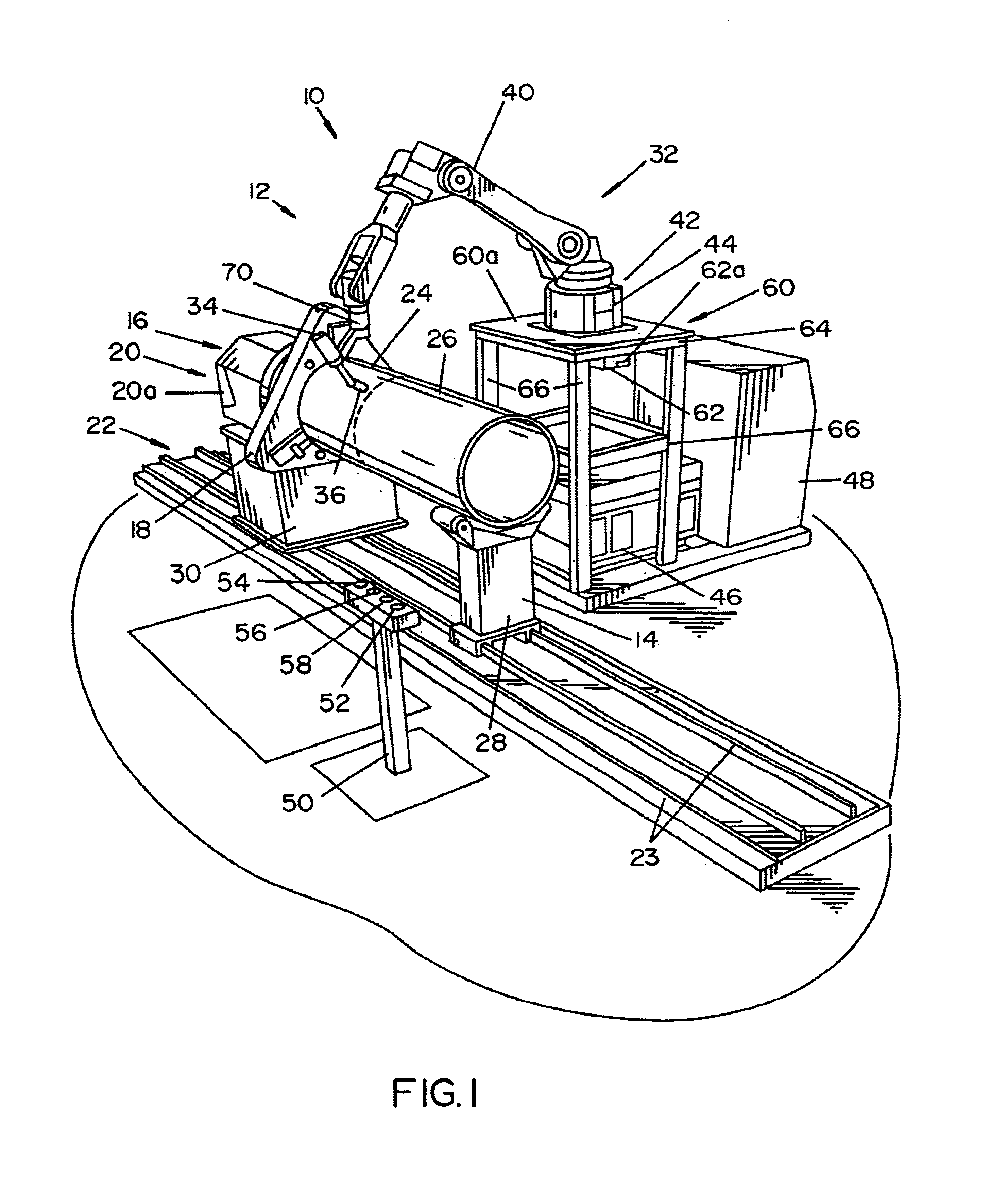
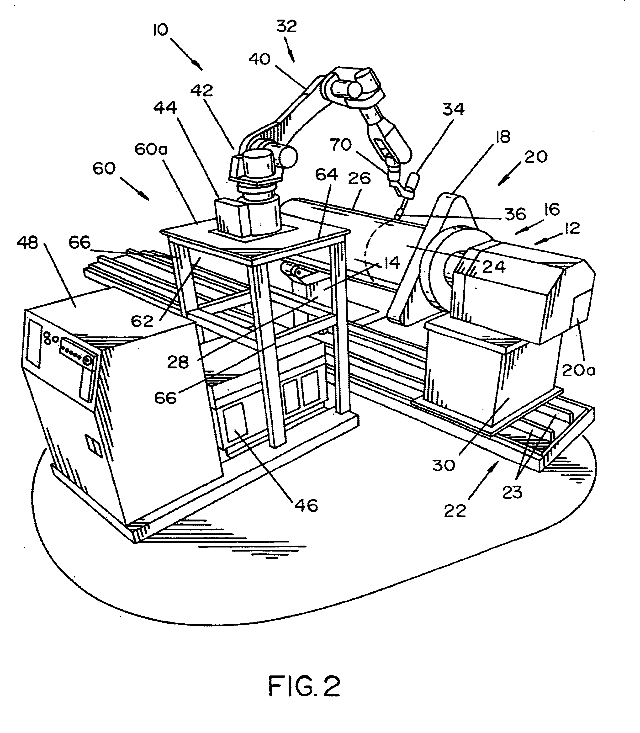
[0031]Referring now to the drawings wherein the drawings are for the purpose of illustrating the preferred embodiments of the invention only, and not for the purpose of limiting same, FIGS. 1 and 2 illustrate a robotic welding system 10 including a workpiece support assembly 12, having an idle arm 14 and head stock 16. Included as part of head stock 16 is a clamp or chuck element 18, and a motor / gear arrangement 20 having a motor controller 20a. The motor of motor / gear arrangement 20 may, in one embodiment, be a servo motor. Idle arm 14 and head stock 16 include wheels, bearings or other mechanisms to interface to a rail system 22, and which permit workpiece support 12 to move along rails 23. Idle arm 14 and head stock 16 each hold at least an end or portion of cylindrical workpiece portions 24 and 26, which are to be welded.

[0032]Idle arm 14 and head stock 16 are further configured with pedestals 28, 30, providing a known distance between the ground and workpiece portions held by w...


PUM

PropertyMeasurementUnit
diameteraaaaaaaaaa
sizeaaaaaaaaaa
lengthsaaaaaaaaaa

Abstract

A first embodiment of the present application is directed to a method and system used to weld a cylindrical workpiece. A substantially cylindrical workpiece is loaded into a workpiece support, and a robotic welding arm is positioned located at a start position. A value representing a size of the cylindrical workpiece is input into a robot controller via a system interface. Inputting of the size value to the robotic interface obtains a control program. Operation of the obtained control program is initiated by an operator, causing the robot arm to move a preprogrammed distance toward a work surface of the workpiece. Then a welding process is performed by the welder carried on the robot arm in accordance with the control program. The process includes initiating operation of the welder, and moving the welder in a pattern appropriate for the welding operation. The workpiece and welder are moved relative to each other so as to perform the welding process as determined by the control program.

Description

INCORPORATION BY REFERENCE[0001]Incorporated by reference are U.S. Pat. Nos. 5,001,326, 5,961,863 and 6,051,810 related to improvements in welding processes. Further incorporated are U.S. Pat. Nos. 6,036,082 and 6,278,074 directed to robotic welding apparatuses, and U.S. Pat. Nos. 5,676,857 and 6,204,478, directed to methods of pipe welding.[0002]The present application relates to the art of welding and, more particularly, to a robotic welding system designed to efficiently weld a cylindrical workpiece.BACKGROUND OF THE INVENTION[0003]The use of robotics to perform welding operations is well known. Typically, robots are used to increase production and / or to reduce human exposure to harsh and / or undesirable working conditions. Such systems may include an arc welding robot which moves a welder toward an object which is fixed to a welding jig. The system welds the object while moving the object and / or the welder. A control program controlling the movement of the robot, operates on the ...

Claims


Application Information

Patent Timeline
Patent Type & Authority Patents(United States)
IPC IPC(8): B23K9/02B23K37/053B23K9/095B23K9/028
CPCB23K9/0216B23K9/0286B23K9/0953B23K37/0538
Inventor LIPNEVICIUS, GEOFF M.
Owner LINCOLN GLOBAL INC
Why Eureka
Try Eureka