[0011]Therefore, to cope with such situations, the present invention is designed. It is an object of the invention to provide an ink tank for which ink can be injected sufficiently and stably without deteriorating the filling efficiency of ink even if the ink tank is made small and flat having wide width and low height.
[0012]Also, it is another object of the invention to provide a small and flat ink tank having wide width and low height, which is capable of carrying out the stable ink supply at high speed corresponding to high-speed recording.
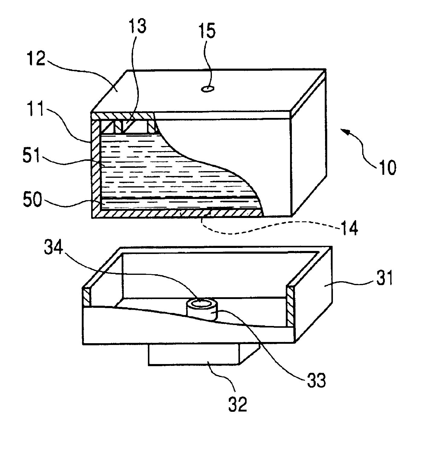
[0014]In accordance with the present invention, on the inner face of the ink tank housing where the ink supply port is open, a first ink holding member is arranged following essentially the shape of this inner face, and also, on this inner face, grooves are arranged and communicated with the ink supply port. In this way, when ink is filled in the ink tank, it is made possible to fill ink in a second ink holding member, which is arranged on the first ink holding member, having smaller ink holding power than that of the first ink holding member, for the first time after ink has been filled entirely in the first ink holding member manner. Then, in this way, when ink is filled, ink can be filled in the second ink holding member almost uniformly on the entire abutting surface on the first ink holding member, thus making it possible to enhance the filling efficiency of ink.
[0017]The ink tank of the present invention in another mode is such that the ink holding power of the first ink holding member is larger than that of the second ink holding member. Therefore, ink in the ink tank is easily retained on the circumference of the external member, which serves as the part to which ink is led out (ink is supplied), and produces the effect that ink in the ink tank is stabilized efficiently. In addition, the first ink holding member is configured to essentially follow the inner shape of the portion of the housing having the ink supply port provided therefor, hence making it possible to carry out the liquid supply stably even when ink is supplied in a large flow rate without being affected by the fluctuation of liquid flow that moves in the second ink holding member when ink is supplied, that is, without being affected easily by the variation of flow resistance (varied concentrations of fibers or the like) in the second ink holding member.
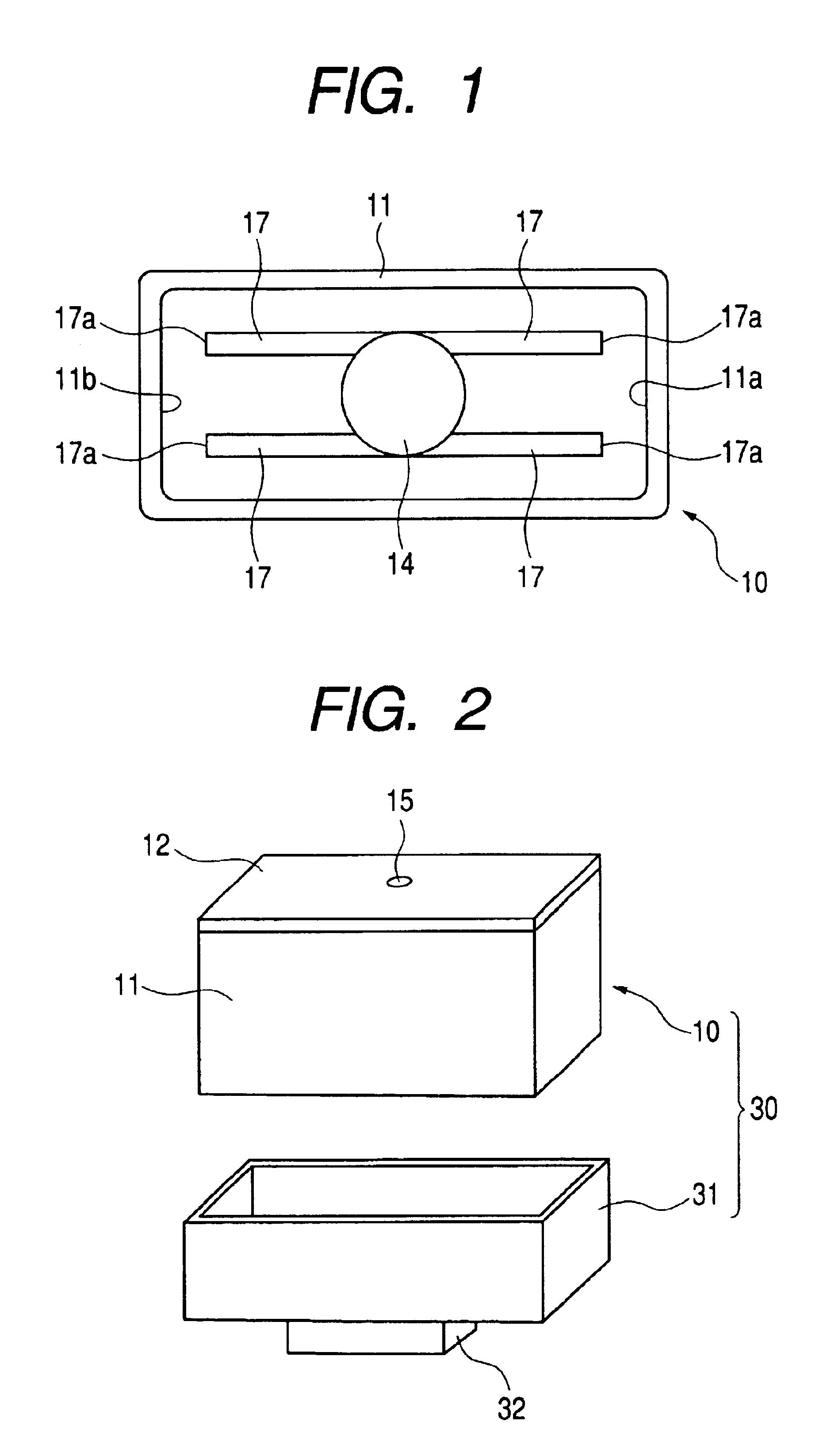
[0019]Further, the first ink holding member is substantially the same shape as the inner face of the housing. Therefore, it is made possible to utilize the inner space of the housing effectively without making the shape of the housing, particular the inner shape thereof, complicated.
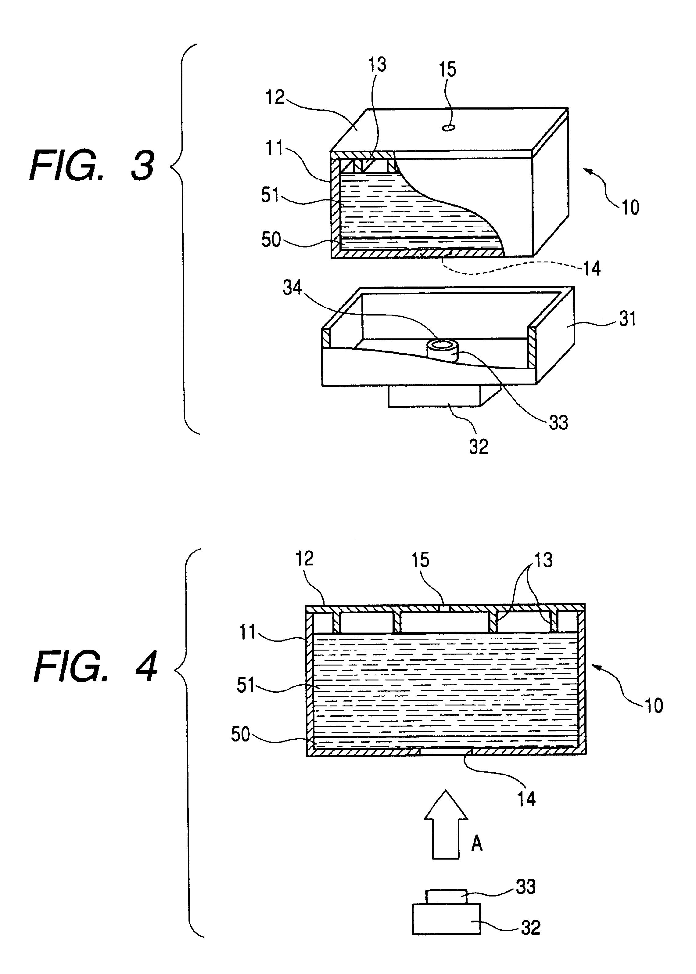
[0020]With the ink holding power of the first ink holding member being larger than that of the second ink holding member, the first ink holding member has relatively more liquid remainders than the second ink holding member after liquid is lead out. As a result, the influence that may be exerted here becomes greater particularly when liquid is supplied at high speed. Therefore, the first ink holding member is arranged to be of
thin sheet type to enable the ink remainders to be reduced by making the content volume of the first ink holding member smaller, while demonstrating the aforesaid effect of the present invention.

