Metal halide accent fixture with adjustable reflector/beam spread

Inactive Publication Date: 2005-09-13
COOPER TECH CO
View PDF10 Cites 29 Cited by
  • Summary
  • Abstract
  • Description
  • Claims
  • Application Information

AI Technical Summary

Benefits of technology

[0006]The focusing sleeve includes internal threads which engage external threads on the intermediate sleeve. Carried within the focusing sleeve is a reflector member having a generally concave interior surface. A lens is secured to the inside of the focusing sleeve and a light-absorbing layer is secured between the reflector member and the lens. The focusing sleeve includes a groove and two internal ridges, one of which serves as a stop for locating the reflector member and the other which cooperates with a locking ring carried in the groove to secure the lens in place. Turning the focusing sleeve also carries the intermediate sleeve causing the focusing sleeve and the reflector member to move axially with respect to the lamp light source, i.e., arc tube. This causes the light output of the light fixture to change from floodlight to spotlight and vice versa.
[0008]The adjustment range of the beam from flood to spot is determined by varying the position of the reflector relative to the elongated arc tube of the lamp. This produces a relatively uniform light level without dark spots across the beam at any position as well as a markedly wide beam spread depending upon the longitudinal adjustment of the apertured reflector.
[0013]Still another feature is the simplicity of the design, which allows lamps of various wattage, e.g. 35 watt or 75 watt, to be produced merely by scaling up or down some of the parts of the fixture.

Problems solved by technology

While fixtures are available with some adjustment in beam spreads, a limited number of beam spreads are available.

Method used


Image

  • Metal halide accent fixture with adjustable reflector/beam spread
  • Metal halide accent fixture with adjustable reflector/beam spread
  • Metal halide accent fixture with adjustable reflector/beam spread

Examples


Embodiment Construction

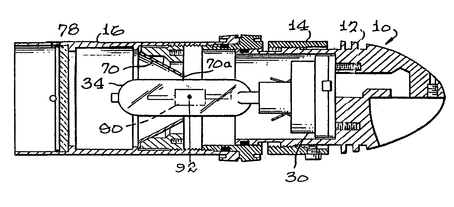
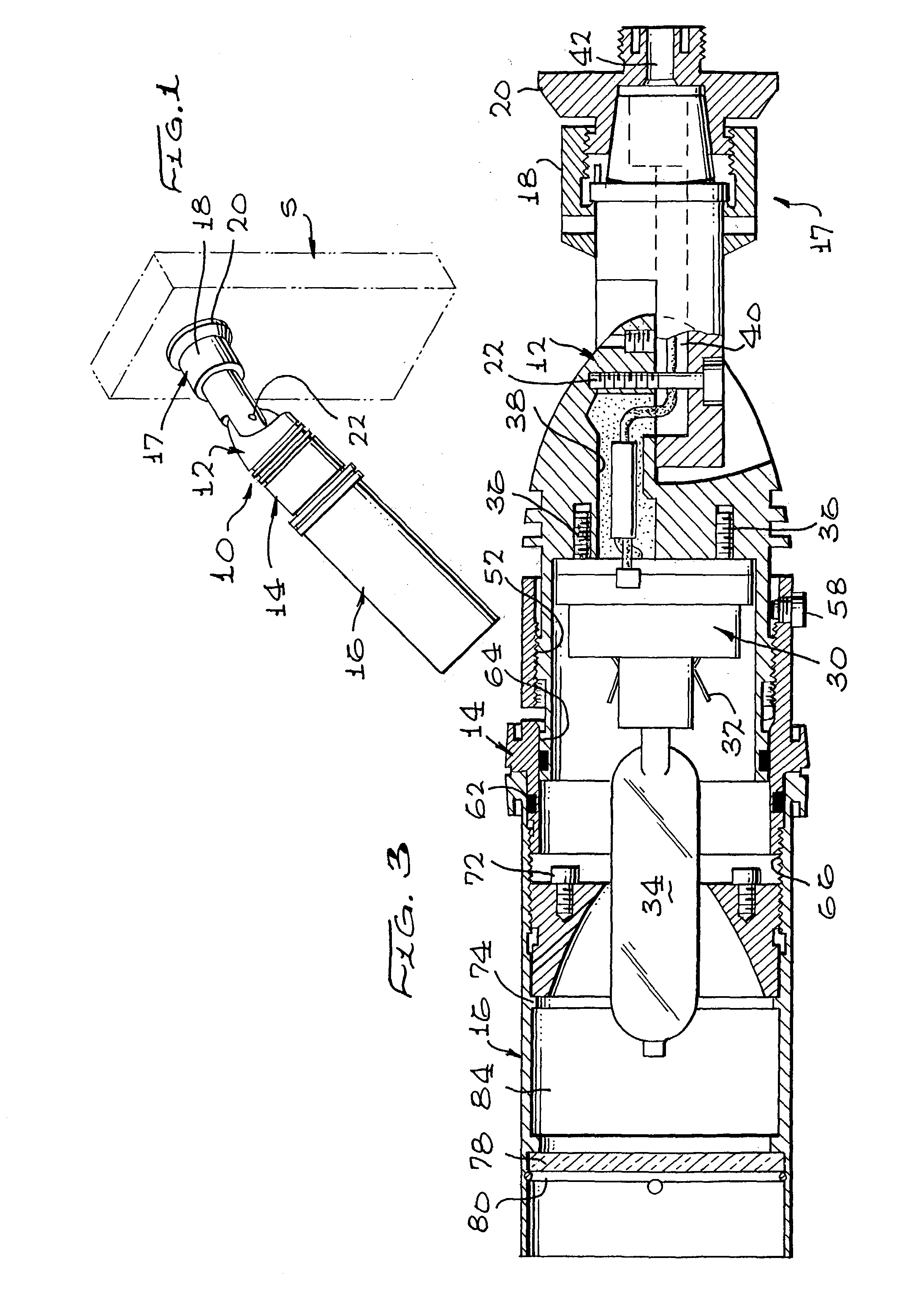
[0022]Referring now to FIG. 1, which is a perspective view of a metal halide lighting fixture 10 according to the invention, fixture 10 includes a lamp housing 12, an intermediate sleeve 14 and a focusing sleeve 16. The lamp housing is secured to a mounting assembly 17 which includes certain parts discussed below, including a flange 20 and a sleeve 18 which is threadedly engaged with flange 20.

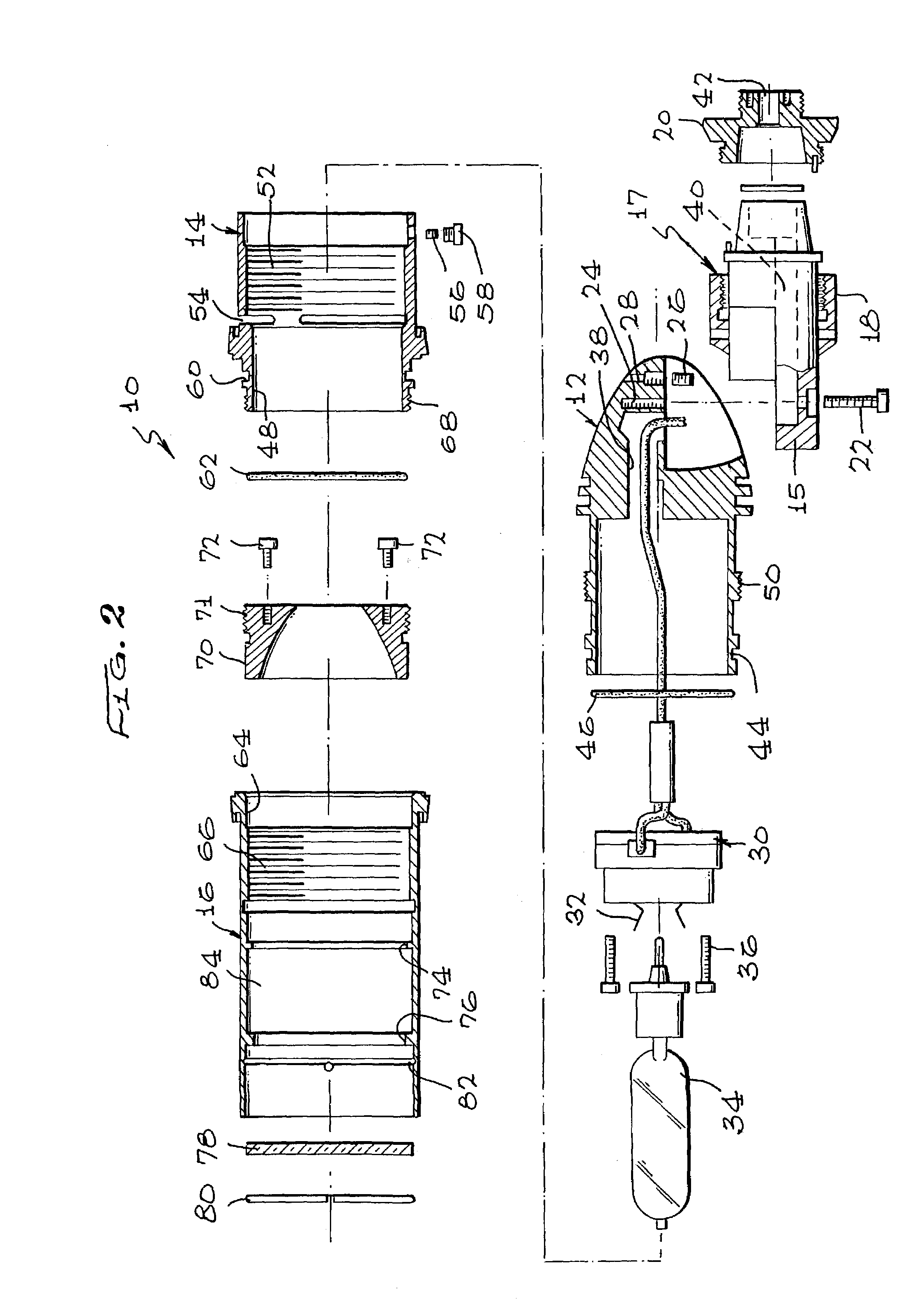
[0023]FIG. 2 is an exploded longitudinal sectional view of the lighting fixture 10 of FIG. 1; and FIG. 3 is a longitudinal sectional view of the fixture as assembled. In FIGS. 2 and 3 are shown the lamp housing 12, the intermediate sleeve 14, and the focusing sleeve 16. Shown separated from lamp housing 12 in FIG. 2 is a mounting assembly 17, which incorporates a body 15, a sleeve 18 and a flange 20 to provide a swivelable mounting structure for lighting fixture 10. Note that mounting assembly 17 is secured to the cut-out portion at the right end of lamp housing 12 by means of a screw 22 passi...


PUM


Abstract

A metal halide light fixture includes three generally cylindrical parts including a lamp housing with a lamp and a lamp socket, an intermediate sleeve member secured to the lamp housing, and a third focusing housing secured to the intermediate sleeve member. The focusing housing includes a reflector member including a concave reflecting surface and a lens. The lamp housing carries a T-6 lamp or similar lamp which includes a cylindrical arc tube having a significant axial length. Rotating the focusing housing moves the reflector member which surrounds the lamp axially relative to the arc tube to shift the light output pattern from floodlight to spotlight. The lamp housing is connected to a mounting structure through a swivel connection. Wires from the lamp socket are fed through a port in the lamp housing and a channel in the mounting structure and are potted in place. Threaded connections between the three principal parts are protected by O-ring seals.

Description

BACKGROUND OF THE INVENTION[0001]This invention relates to lighting fixtures, and more importantly to fixtures usable for indoor or outdoor lighting and which are adjustable to provide various beam spreads.[0002]A particular lighting fixture type may need to be adjustable to provide various beam spreads to accomplish a given task; e.g., in one location a fixture may require a wide spread to illuminate a specified area and in another location may require more intense illumination over a smaller area. While fixtures are available with some adjustment in beam spreads, a limited number of beam spreads are available.[0003]There is a need for a low cost, compact, metal halide lighting fixture which is suitably sealed to permit outdoor installation and which is adjustable to provide an infinite range of beam spreads from a spotlight to floodlight, while maintaining a relatively uniform intensity across the beam, particularly without low intensity or dark spots at different beam spreads. Su...

Claims


Application Information

Patent Timeline
Patent Type & Authority Patents(United States)
IPC IPC(8): F21V7/04F21V7/00F21V21/14F21V17/02F21S8/00F21V17/00F21V14/04F21V14/00F21V21/30F21V31/03
CPCF21V14/04F21V17/02F21V21/30F21V31/03
Inventor LEVASSEUR, CRAIG
Owner COOPER TECH CO
Why Eureka
Try Eureka