Metal halide lamp and automotive headlamp apparatus
a technology of metal halide lamps and headlamps, which is applied in the direction of discharge tube main electrodes, fixed installations, lighting and heating devices, etc., can solve the problems of low lamp voltage, low luminous efficiency, and high color deviation
- Summary
- Abstract
- Description
- Claims
- Application Information
AI Technical Summary
Problems solved by technology
Method used
Image
Examples
first embodiment
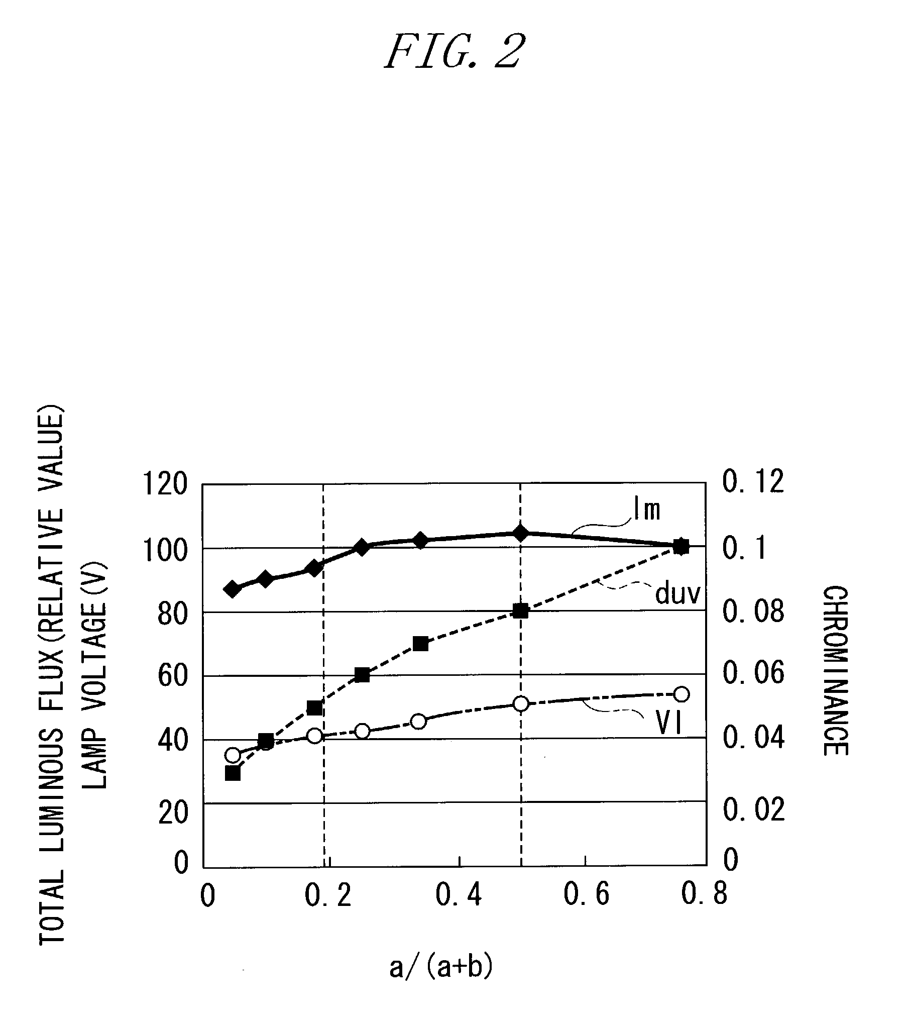
[0124] FIG. 7 is a graph showing an effect of a variation of the ratio a / (a+b) on the rising characteristics of the luminous flux in the example of the metal halide lamp according to the invention. In this drawing, the horizontal axis indicates the ratio a / (a+b), and the vertical axis indicates the time (seconds) required for 80% of the total luminous flux to be attained. The measurement was conducted in such a manner that a lamp power of 85 W, which approximately equals to 2.5 times a lamp power of 35 W in a stable state, was supplied immediately after activation of the metal halide lamp.
[0125] As can be seen from this drawing, within the range of 0.25
[0126] FIG. 8 is a graph showing a variation of the total luminous flux due to a change of the sum of the first and second halides in the example of the metal halide lamp according to the first embodiment of the invention. In this drawing, the...
second embodiment
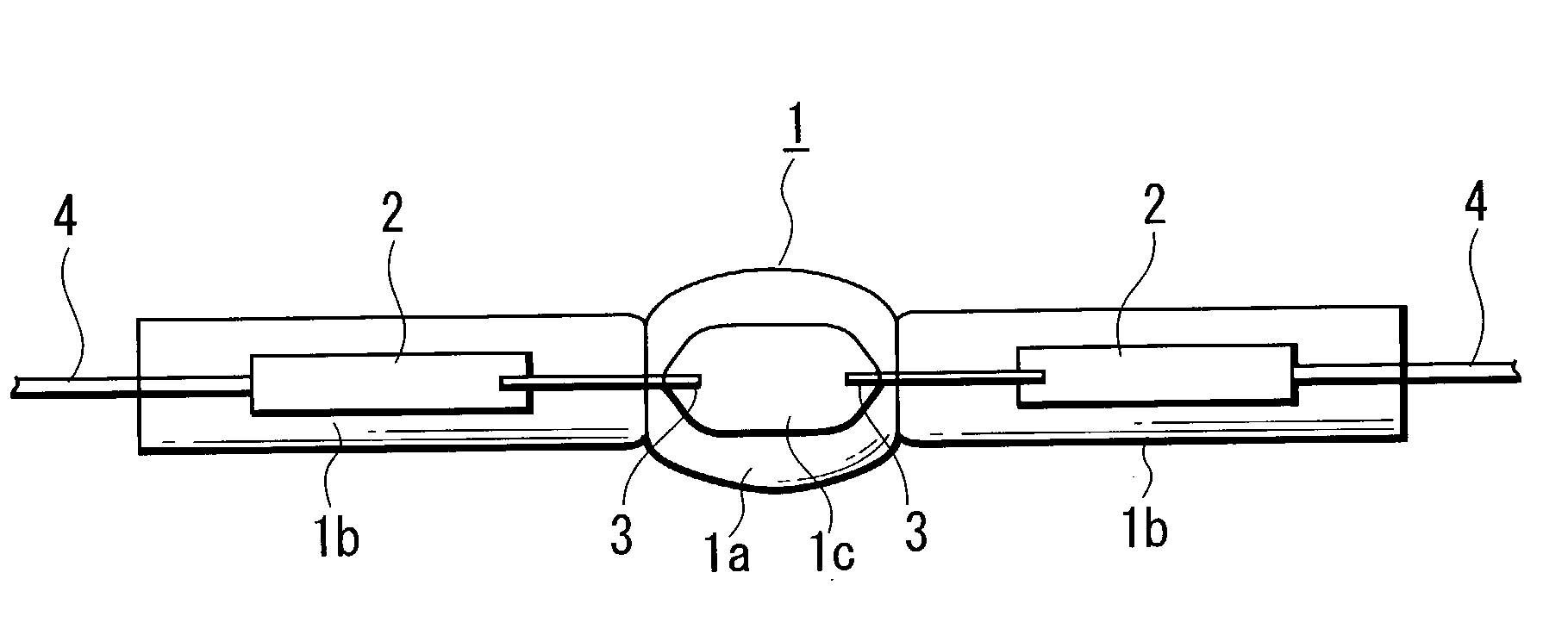
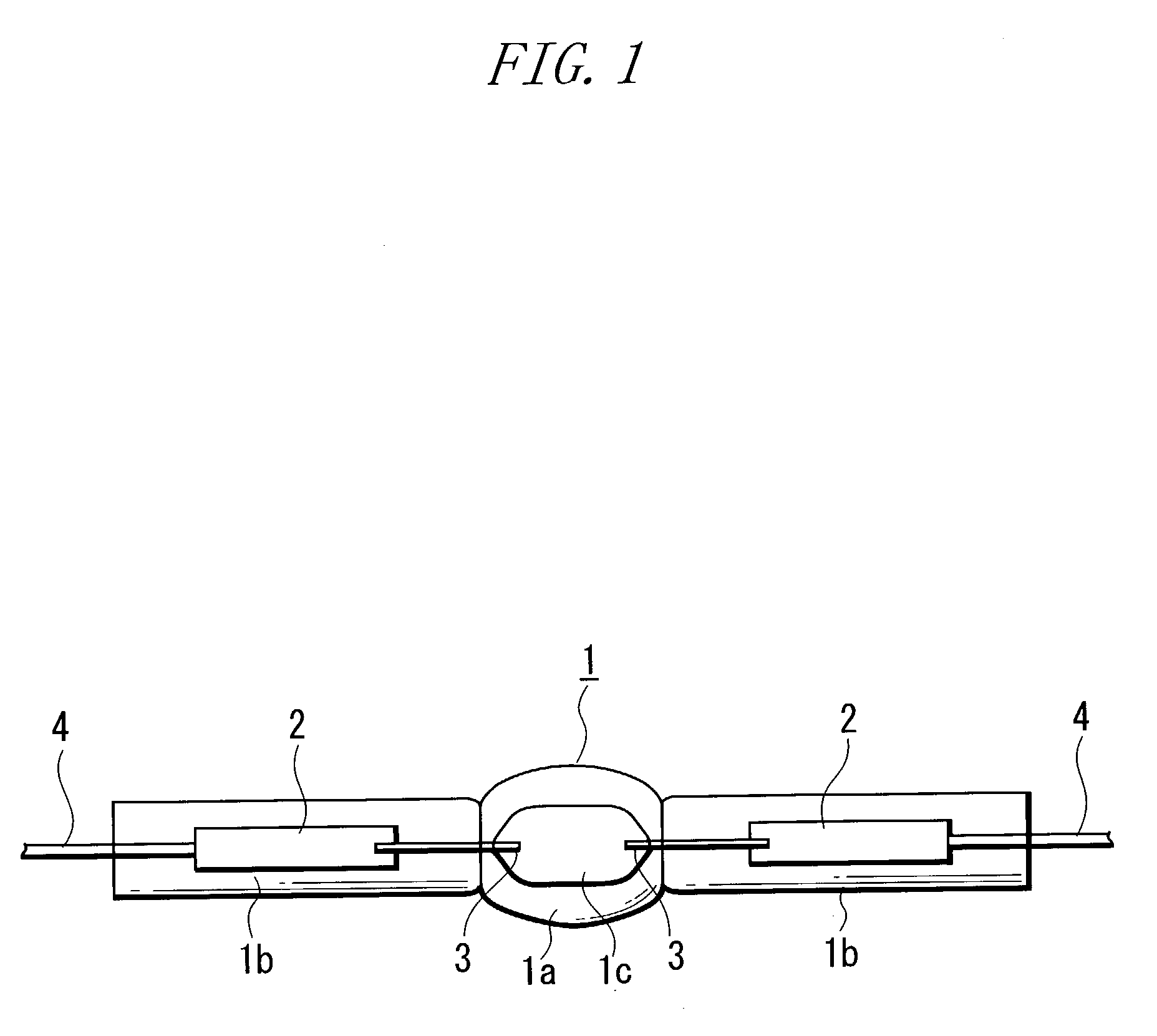
[0128] FIG. 9 is a front view of a metal halide lamp, which is a high voltage discharge lamp according to the invention. According to this embodiment, the metal halide lamp as shown in FIG. 1 is adapted to be installed in an automotive headlamp. In this drawing, reference numeral 7 denotes an outer envelope, reference numeral 8 denotes a cap, reference character ol denotes an external lead, reference character cc denotes a connection conductor, reference numeral 9 denotes an insulating tube, and reference numeral 10 denotes an arc tube.
[0129] The outer envelope 7 has a capability of blocking ultraviolet rays and houses the arc tube 10 having the structure shown in FIG. 1. Both ends of the outer envelope 7 are glass-welded to sealing parts 1b, while the end thereof located nearer the tip is designed to allow ventilation. A light-shielding film 7a is formed at a desired area of the outer surface of the outer envelope 7. The light-shielding film 7a is formed by melting a mixture of a p...
PUM
 Abstract
Description
Claims
Application Information
 - R&D
- Intellectual Property
- Life Sciences
- Materials
- Tech Scout
- Unparalleled Data Quality
- Higher Quality Content
- 60% Fewer Hallucinations
Browse by: Latest US Patents, China's latest patents, Technical Efficacy Thesaurus, Application Domain, Technology Topic, Popular Technical Reports.
© 2025 PatSnap. All rights reserved.Legal|Privacy policy|Modern Slavery Act Transparency Statement|Sitemap|About US| Contact US: help@patsnap.com


