
Metal halide lamp with halogen-promoted wall cleaning cycle

a technology of halide lamps and halogen-promoted wall cleaning cycles, which is applied in the manufacture of electric discharge tubes/lamps, cold cathode manufacture, electrode systems, etc., can solve the problems of light output decline, achieve improved performance and lumen maintenance, and reduce wall blackening

Inactive Publication Date: 2009-06-11
GENERAL ELECTRIC CO
View PDF14 Cites 21 Cited by
  • Summary
  • Abstract
  • Description
  • Claims
  • Application Information

AI Technical Summary

Benefits of technology

[0009]One advantage of at least one embodiment is the provision of a ceramic arc tube fill with improved performance and lumen maintenance.
[0010]Another advantage of at least one embodiment resides in reduced wall blackening.
[0011]Another advantage is that a tungsten regeneration cycle is maintained between a wall of a discharge vessel and a portion of an electrode that is operating at a higher temperature than the wall.

Problems solved by technology

Such lamps often have a light output that diminishes over time due to blackening of the discharge vessel walls.

Method used


Image

  • Metal halide lamp with halogen-promoted wall cleaning cycle
  • Metal halide lamp with halogen-promoted wall cleaning cycle
  • Metal halide lamp with halogen-promoted wall cleaning cycle

Examples


example

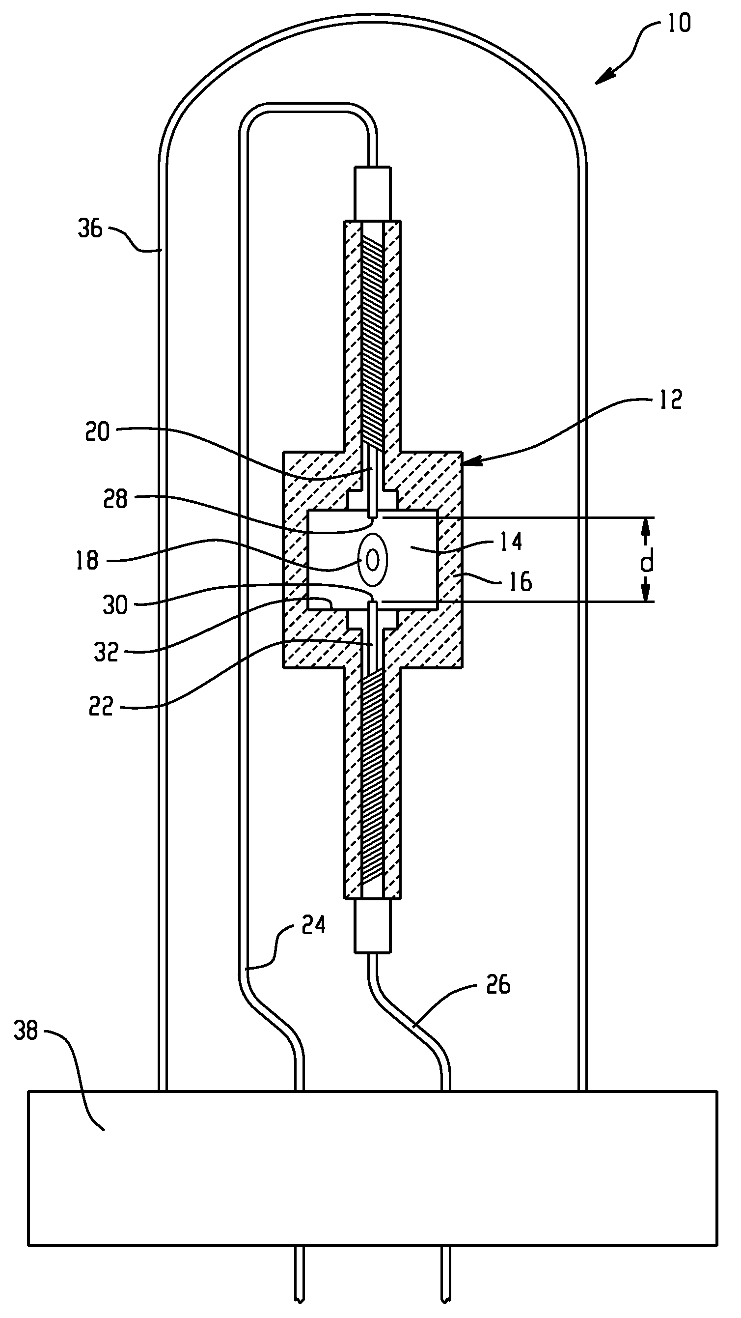
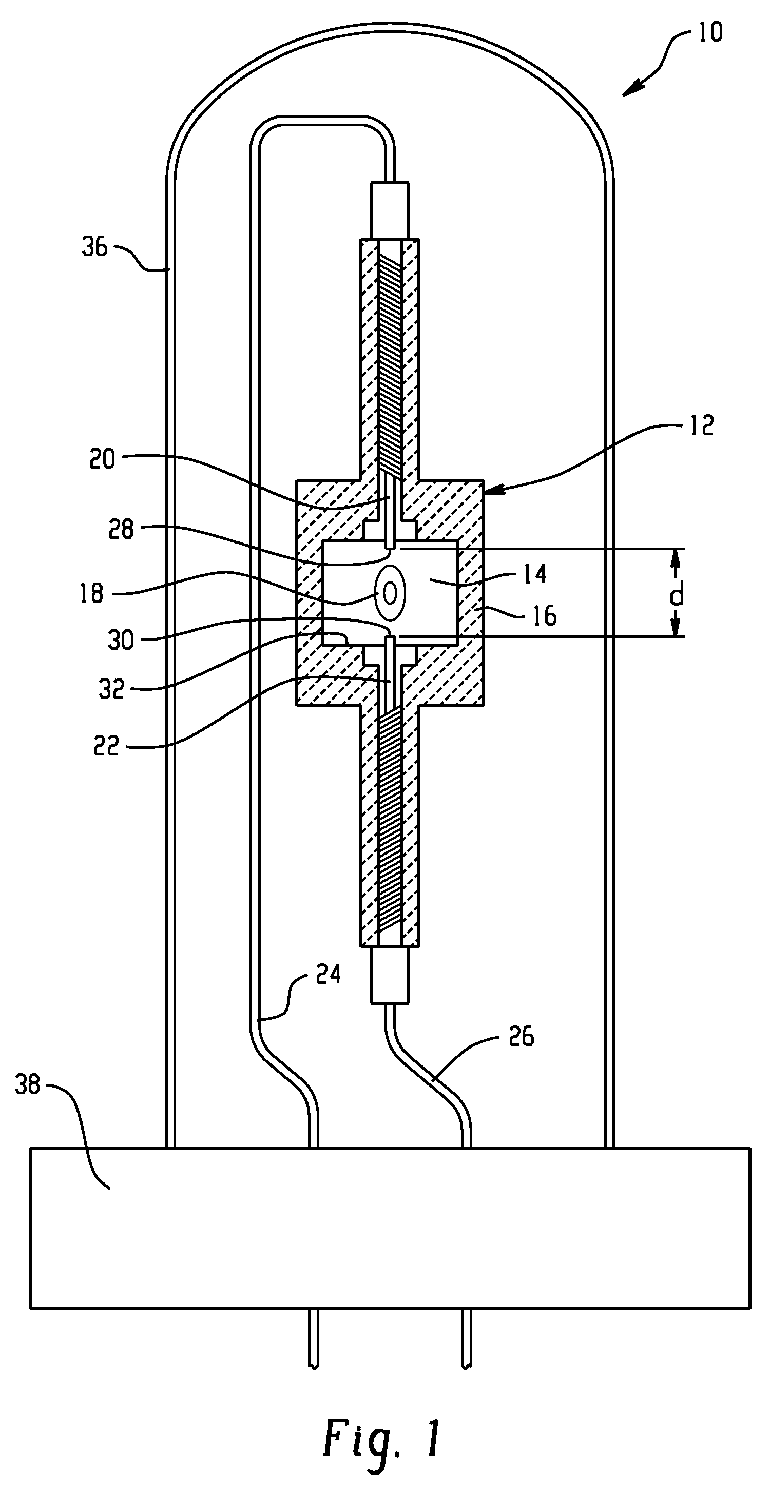
[0062]Arc tubes 12 were formed according to the shape shown in FIG. 1 from three component parts. The internal volume was 0.2 cm3. The lamps were each filled with a fill as shown in Table 2. The fills of exemplary lamps B, C, D, and F also contained Hg (137 μmol / cm3), NaI (107 μmol / cm3), CaI2 (38 μmol / cm3), TlI (3 μmol / cm3) Ar (12 μmol / cm3). Lamps A and E had fills similar to the exemplary lamps, but with no HgI2 or WO3.

TABLE 2TestHgI2WO3A (Control for B, C——and D)B0.04 mg—(0.4 μmol / cm3)C0.16 mg—(1.6 μmol / cm3)D—0.064 mg(1.4 μmol / cm3)E (control for F)——F 0.3 mg(0.3 μmol / cm3)

[0063]The lamps were run in a standard burning cycle (11 hrs. on followed by 1 hour off) for extended periods in a horizontal orientation (i.e., at 90 degrees to that illustrated in FIG. 1) on a ballast at 70 W.

[0064]Table 3 shows the results obtained after 100 hrs. V is the burning voltage. Lumens is the lumen output of the lamp. X color and Y color are the chromaticity X and Y, respectively, on a standard CIE (C...


PUM


Abstract

A lamp includes a discharge vessel. Tungsten electrodes extend into the discharge vessel. An ionizable fill is sealed within the vessel. The fill includes a buffer gas, optionally free mercury, a halide component which includes a rare earth halide selected from the group consisting of lanthanum halides, praseodymium halides, neodymium halides, samarium halides, cerium halides, and combinations thereof, a source of available halogen. The discharge vessel optionally includes a source of available oxygen. The source of available halogen and optional source of available oxygen are present in an amount such that the vapor phase solubility of tungsten species in the fill during lamp operation is lower adjacent at least a portion of one of the electrodes than at a wall of the discharge vessel, such that tungsten deposited on the wall during lamp operation is transported back to the electrode.

Description

BACKGROUND OF THE INVENTION[0001]The present invention relates to a discharge lamp with high lamp lumen maintenance. It finds particular application in connection with a ceramic metal halide (CMH) lamp with a source of available halogen in the fill and will be described with particular reference thereto.[0002]High Intensity Discharge (HID) lamps are high-efficiency lamps that can generate large amounts of light from a relatively small source. These lamps are widely used in many applications, including highway and road lighting, lighting of large venues such as sports stadiums, floodlighting of buildings, shops, industrial buildings, and projectors, to name but a few. The term “HID lamp” is used to denote different kinds of lamps. These include mercury vapor lamps, metal halide lamps, and sodium lamps. Metal halide lamps, in particular, are widely used in areas that require a high level of brightness at relatively low cost. HID lamps differ from other lamps because their functioning ...

Claims


Application Information

Patent Timeline
Patent Type & Authority Applications(United States)
IPC IPC(8): H01J61/22H01J61/12
CPCH01J61/125H01J61/827H01J61/26
Inventor RUSSELL, TIMOTHY D.RAHMANE, MOHAMEDMESCHTER, PETER J.UTTERBACK, GARY W.
Owner GENERAL ELECTRIC CO
Learn More