

Orthodontic bracket
a bracket and orthodontic technology, applied in the field of brackets for orthodontic treatment, can solve the problems of reducing the retention force of the bracket structure, reducing the service life of the bracket, and easily getting lost, and achieves the effect of high torque, high closing force, and avoiding increasing the risk of spring damage during opening
- Summary
- Abstract
- Description
- Claims
- Application Information
AI Technical Summary
Benefits of technology
Problems solved by technology
Method used
Image

Examples
Embodiment Construction
[0035]The invention will now be explained in detail with reference to the drawings.
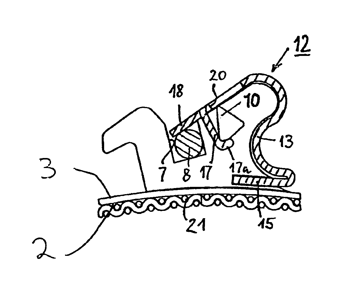
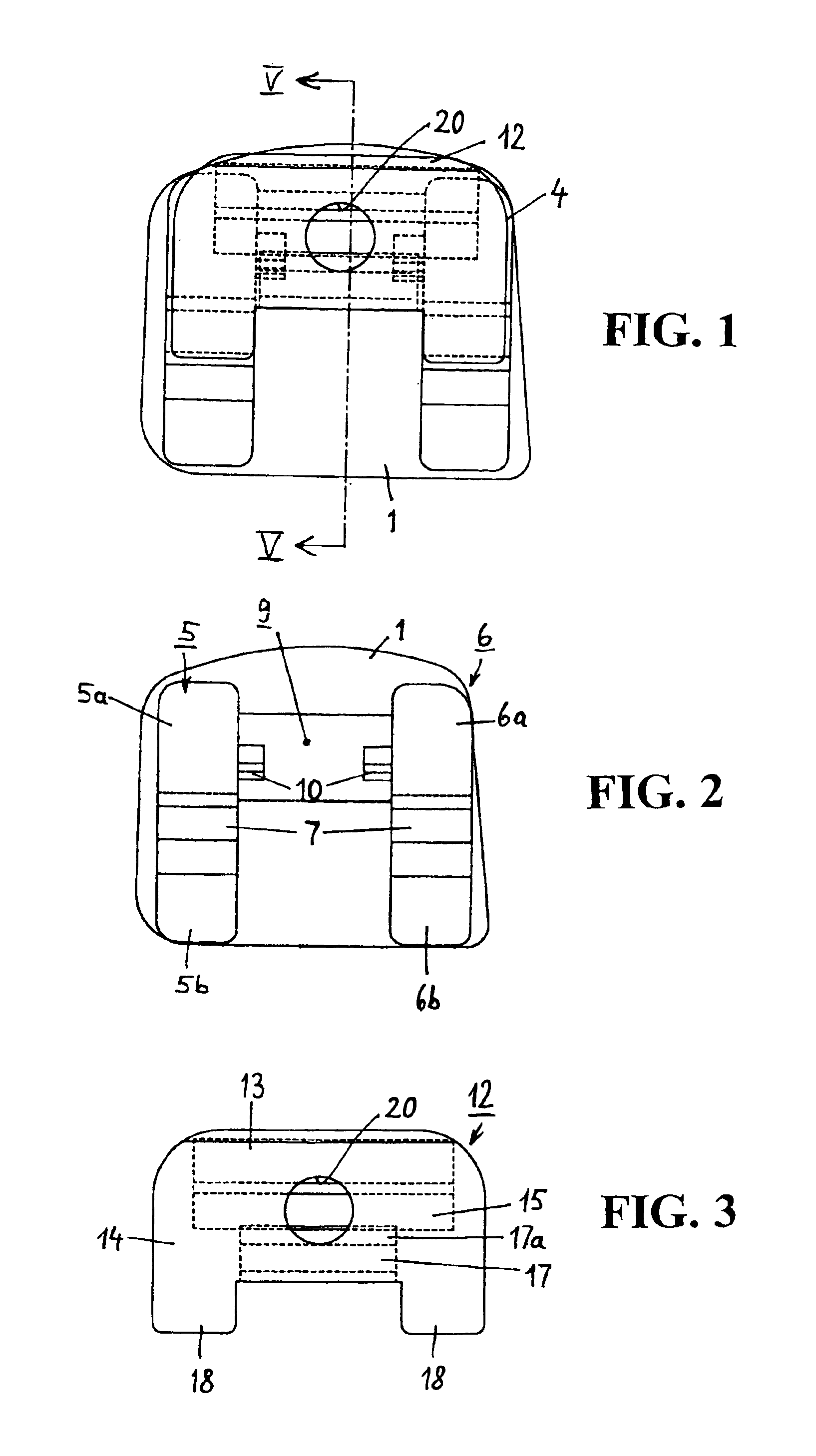
[0036]As shown in FIGS. 1 to 3, the bracket consists of a base plate 1, which comprises a bottom side 2 (see FIG. 5) and a top side 3 from which a structure 4 arises.
[0037]The base plate 1 has an irregular contour, since this contour is adapted to the contour of the crown of a tooth at which the specially shown bracket is adapted to be attached.
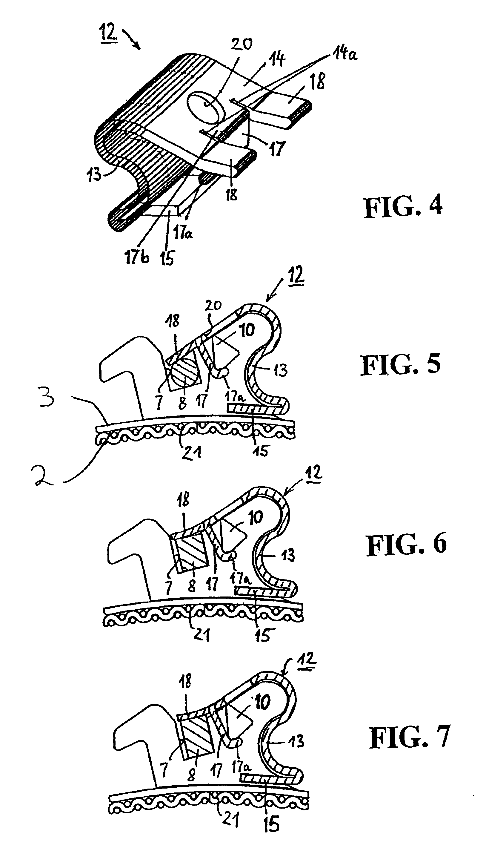
[0038]The structure 4 has two mesial and distal wings S and 6 opposing each other at a mutual distance and divided into gingival and incisal sections 5a, 6a and 5b, 6b, respectively. For example, sections 5a and 5b are easily discerned in FIG. 15 which shows mesial wing 5. Sections 5a and 5b are separated from one another by a slot 7 extending between them which is adapted to receive an arch wire 8. Examples of such arch wires are shown in FIGS. 5 to 7. In the following, slot 7 is called arch wire slot.
[0039]Gap 9 separates the mesial and distal wings 5 and 6 f...
PUM
 Abstract
Description
Claims
Application Information