
Container with snap-in closure

a technology of snap-in closure and container, which is applied in the field of containers, can solve the problems of high snap-in force generation, and achieve the effect of low cost and good operability

Active Publication Date: 2010-03-23
ROESLER PETER
View PDF10 Cites 14 Cited by
  • Summary
  • Abstract
  • Description
  • Claims
  • Application Information

AI Technical Summary

Benefits of technology

[0004]It is therefore an object of the claimed invention to disclose a container comprising a snap-in closure of the aforementioned type in such a way that the snap-in closure offers a strong holding force combined with low cost and good operability.
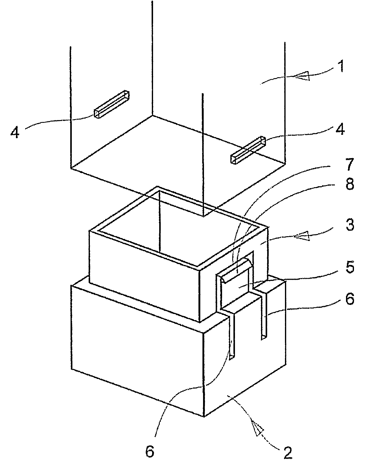
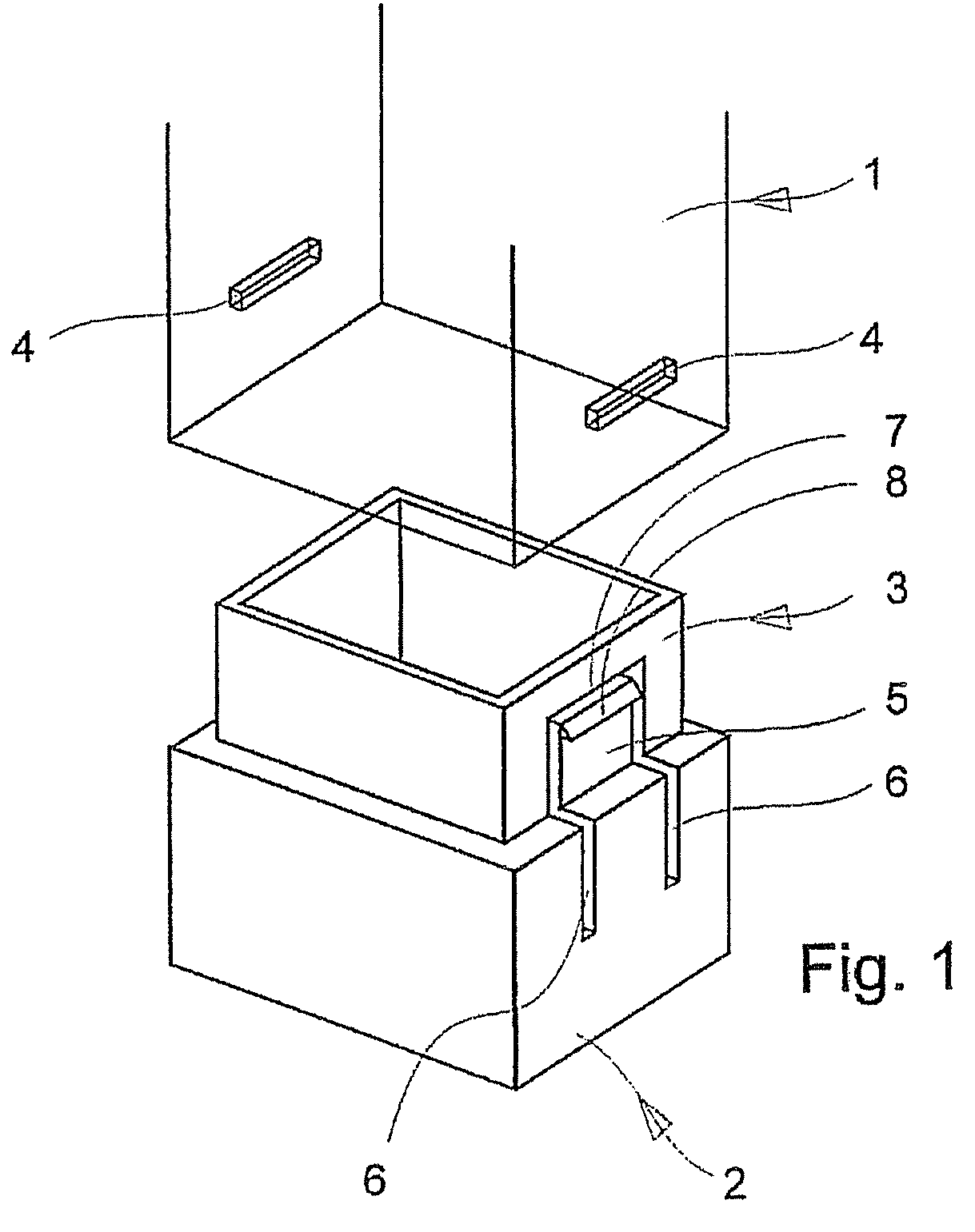
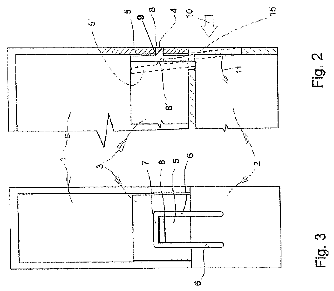
[0006]Based on the enabling disclosure, the substantial advantage of the claimed invention is that a snap-in tab is formed out of and / or detached from the wall of one container part. A substantially high spring force is generated by the snap-in tab since normally containers of this type have a wall thickness of about 0.5 to 2.0 mm and very high closure forces can be generated with the selection of a suitable synthetic material. The detachment of the snap-in tab from the wall of one container part provides a good spring action that can be effected for the snap-in tab. The snap-in force of the snap-in tab is determined during manufacture and is related to the length of the detachment. In an example, a snap-in key is disposed at the upper free end of the snap-in tab. Sharp-edged surfaces of the snap-in tab can engage a coordinated snap-in slit on the opposite container part. The opposing sharp-edged surfaces result in the generation of high snap-in forces that are able to withstand even the corresponding opening forces acting on the container parts.

Problems solved by technology

The opposing sharp-edged surfaces result in the generation of high snap-in forces that are able to withstand even the corresponding opening forces acting on the container parts.

Method used


Image

  • Container with snap-in closure
  • Container with snap-in closure
  • Container with snap-in closure

Examples


Embodiment Construction

[0014]The container according to FIGS. 1 through 3 comprises an upper part 1 and a lower part 2 that snaps into the upper part 1. The two parts 1, 2 may be constructed of any desired material composition, such as for example, metal, synthetic materials, composite materials, and other similar materials. The two parts 1, 2 may be constructed as transparent, partially transparent, or not transparent. The terms “upper part” and “lower part” are interchangeable. It is therefore not important in which part 1, 2 the snap-in closure with the snap-in device 5, described below, is constructed. In the example of an embodiment shown in FIG. 1, the snap-in closure is disposed in or constructed out of a wall of the lower part 2 of the container. It is also advantageous that the lower part 2 of the container comprises a lower part of greater dimensions changing into an upper socket-type part 3 having smaller dimensions and being open on top. The construction of the snap-in device in the area of th...


PUM

PropertyMeasurementUnit
thicknessaaaaaaaaaa
dimensionaaaaaaaaaa
spring forceaaaaaaaaaa

Abstract

A container comprising a snap-in closure disposed between an upper part and a lower part of the container, the snap-in closure having a relatively strong holding or locking force and able to be opened relatively easily. The snap-in closure comprises a snap-in tab constructed out of the wall of one part of the container and detached along three sides, with a snap-in key disposed at the upper free end of the said snap-in closure and able to engage in a coordinated snap-in slit at the opposite container part.

Description

CLAIM OF PRIORITY[0001]This invention claims the benefit of German Application No. 20 2005 007 586.8, filed on May 13, 2005.FIELD OF THE INVENTION[0002]The claimed invention is a container comprising a snap-in closure disposed between an upper and a lower part, and specifically a container wherein the snap-in closure has a relatively strong locking force and is able to be opened easily.BACKGROUND OF THE INVENTION[0003]Containers having snap-in closures are known to the art in various embodiments. For example, it is known in the art to dispose a snap-in closure between an upper part and a lower part of a container, where the snap-in closure is constructed as knob closure. Such a closure, although easy to open, has a very weak holding or locking force. In order to store relatively heavy objects in a container, however, it is necessary to provide a snap-in closure that has a strong holding force and that facilitates construction at relatively low manufacturing costs.SUMMARY OF THE INVE...

Claims


Application Information

Patent Timeline
Patent Type & Authority Patents(United States)
IPC IPC(8): B65D41/16A45C13/10E05C9/00E05C19/10E05C19/06E05C19/00B65D41/18A45C13/18B65D39/00B65D43/02
CPCB65D43/021B65D2543/00101B65D2543/00277B65D2543/00296B65D2543/00314B65D2543/00509B65D2543/00574B65D2543/00666B65D2543/00694B65D2543/0074B65D2543/00805B65D2543/00925Y10S206/806Y10T292/42Y10T292/0895Y10T292/083Y10T292/438
Inventor ROESLER, PETER
Owner ROESLER PETER
Learn More