Optical sensor device
a sensor device and optical sensor technology, applied in the field of optical sensor devices, can solve the problems of low adhesion of the surface of the metal to the resin, low force of the lead, and prone to cracking, etc., to achieve high adhesion, less prone to stress, and high air tightness
- Summary
- Abstract
- Description
- Claims
- Application Information
AI Technical Summary
Benefits of technology
Problems solved by technology
Method used
Image
Examples
first embodiment
[0038]Now, a configuration of an optical sensor device according to a first embodiment of the present invention is described with reference to the drawings.
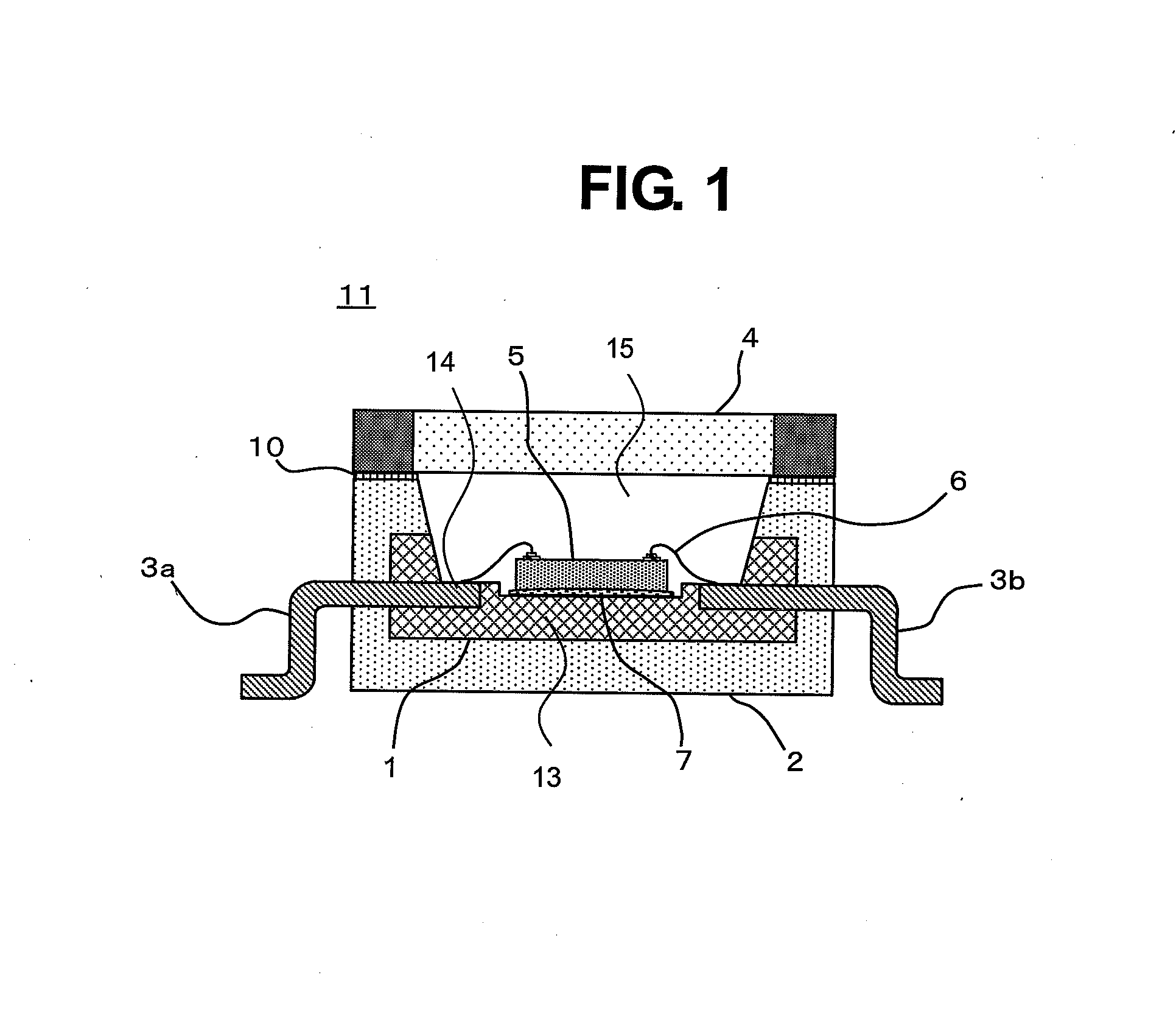
[0039]FIG. 1 is a schematic vertical sectional view of an optical sensor device 11 according to this embodiment. A resin molded portion having a cavity 15 is formed of a double molding structure in which a first resin molded portion 1 and a second resin molded portion 2 are subjected to contact fitting molding. The first resin molded portion 1 has a structure in which a part of leads 3a and 3b made of metals is subjected to contact fitting molding through use of a resin, and an element mounting portion 13 is integrally molded on a bottomed portion of the cavity 15. The peripheries of the leads 3a and 3b, excluding a wire bonding portion 14 and a portion exposed to outside through a package as an external lead terminal, are molded with the first resin molded portion 1. The periphery of the first resin molded portion 1 is subjected...
second embodiment
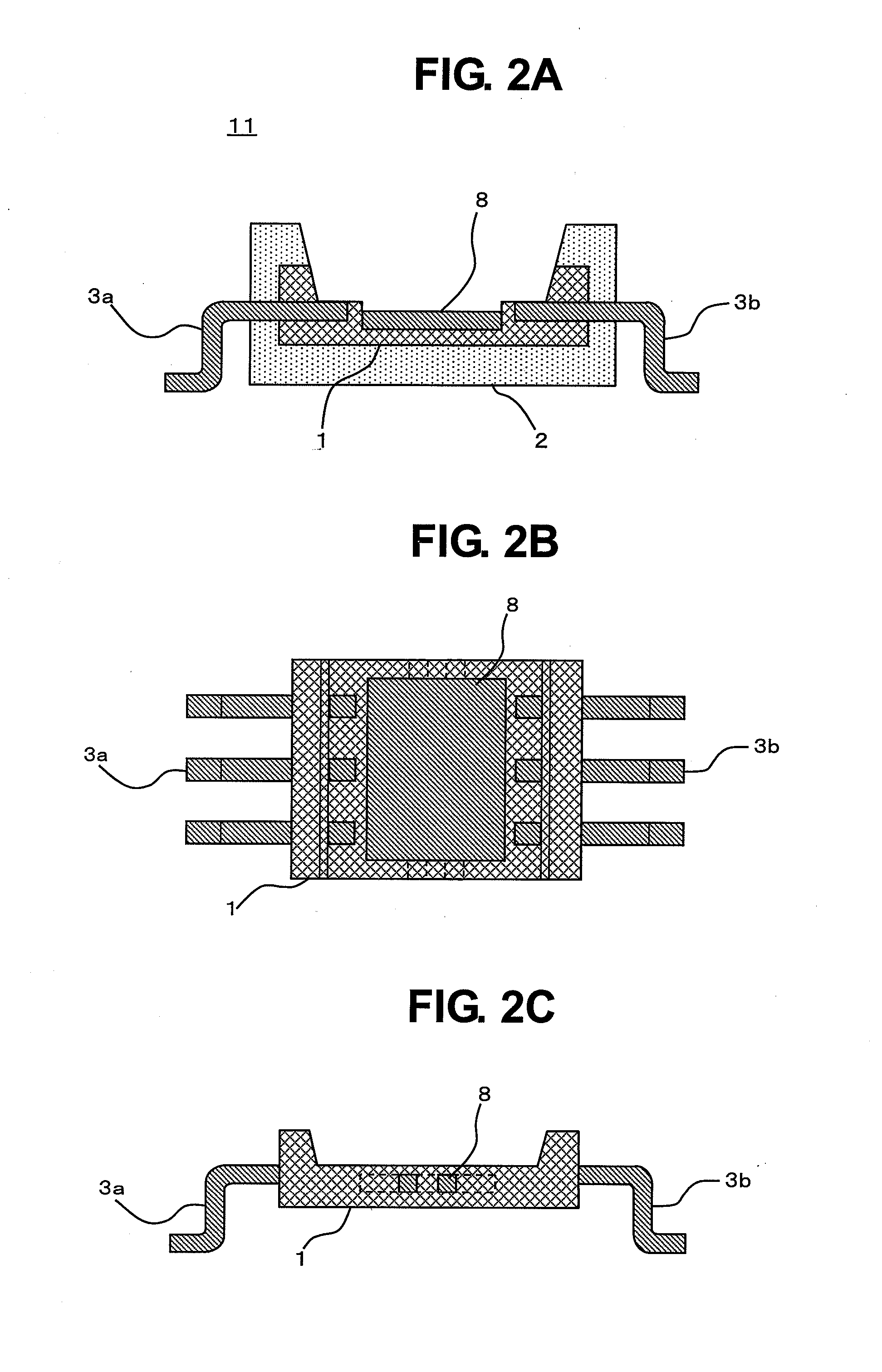
[0046]FIG. 2A is a sectional view of an optical sensor device 11 according to a second embodiment of the present invention. FIG. 2B is a front view of a first resin molded portion 1, and FIG. 2C is a sectional view thereof. FIG. 2A illustrates a cross section of a package body having a cavity, excluding a glass substrate 4 having a filter function, in the optical sensor device 11. The optical sensor device 11 has a structure in which a die pad portion 8 formed of a metal frame is provided on the first resin molded portion 1. The first resin molded portion 1 has a structure in which the periphery of the die pad portion 8 formed of a metal frame, excluding a surface side on which an optical sensor element 5 is to be mounted, and the periphery of each lead, excluding a portion in which a frame surface to be used as a wire bonding portion is exposed, are molded with a resin so as to be integrated.
[0047]Further, FIG. 2B illustrates a front view of the first resin molded portion 1 having ...
third embodiment
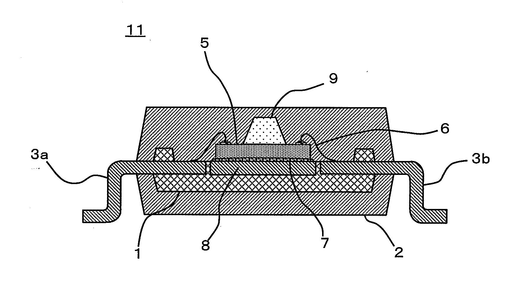
[0048]FIG. 3 is a sectional view of, an optical sensor device 11 according to a third embodiment of the present invention. In a first resin molded portion 1, a part of a die pad portion 8 formed of a metal frame on which an optical sensor element 5 is to be mounted is molded so as to increase thickness, and a bottom surface of the die pad portion 8 on which the optical sensor element 5 is to be mounted is exposed from a surface of a second resin molded portion 2 corresponding to a back surface of a package. The bottom surface of the die pad portion 8 is not covered with a resin forming the second resin forming portion 2. Thus, a double molding structure is achieved which has a heat dissipation function capable of releasing heat, generated from the mounted optical sensor element 5, to outside through an adhesive 7 via the die pad portion 8.
PUM
 Abstract
Description
Claims
Application Information
 - R&D
- Intellectual Property
- Life Sciences
- Materials
- Tech Scout
- Unparalleled Data Quality
- Higher Quality Content
- 60% Fewer Hallucinations
Browse by: Latest US Patents, China's latest patents, Technical Efficacy Thesaurus, Application Domain, Technology Topic, Popular Technical Reports.
© 2025 PatSnap. All rights reserved.Legal|Privacy policy|Modern Slavery Act Transparency Statement|Sitemap|About US| Contact US: help@patsnap.com


