Carburetor arrangement of a portable handheld work apparatus

a portable handheld, work apparatus technology, applied in the direction of liquid fuel feeders, machines/engines, separation processes, etc., can solve the problems of insufficient elastic return formability of the pump bellows, unfavorable air/fuel mixture reliably being adjusted exclusively, and high pump force, etc., to achieve low pump work, high elasticity, and reliable venting

Inactive Publication Date: 2005-09-06
ANDREAS STIHL AG & CO KG
View PDF11 Cites 14 Cited by
  • Summary
  • Abstract
  • Description
  • Claims
  • Application Information

AI Technical Summary

Benefits of technology

[0007]It is an object of the invention to provide a carburetor arrangement of the kind described above which is so improved that a reliable acceleration performance is given over a wider operating range with a good effectiveness of the venting pump.
[0010]In an advantageous further embodiment, the supporting means are so configured that they are actuable by the one-sided pressure on the outflow end of the check valve. In this arrangement, the closing force of the pretensioning means is selected to be so high that the check valve remains closed even for a sudden actuation of the throttle and the high difference pressure in the fuel arising therefrom between both ends of the check valve. When actuating the venting pump, an underpressure arises only at the outflow end of the check valve. This underpressure acts via the support means in a supporting manner on the valve body. In a corresponding embodiment, slight suction forces of the accelerator pump can be adequate to open the check valve. A reliable venting can be achieved with a low pump work and with a pump bellows of high elasticity and low return forces.
[0011]In an advantageous embodiment, the support means include a drive in the form of a membrane. One side of the membrane is charged with the pressure in the venting line and the other side of the membrane is charged with the ambient pressure. High supporting forces can be made available with low constructive complexity via the comparatively large-area membrane. High differences between the closing forces during an acceleration operation and the opening force during the pump operation can be achieved. A further increase of this difference can be achieved in a simple manner via an arrangement of a lever. The membrane operates on the valve body via this lever. The lever can be used, as required, for redirecting the membrane movement into a suitable movement of the valve body. By selecting the lever geometry, the force, which is needed for opening or closing the valve, can be precisely adapted.
[0012]The valve body is configured as an axially displaceable pin having a conically-shaped valve head for engaging in an annularly-shaped seal seat. The conically-shaped valve body is self centering in the annularly-shaped seal seat and leads to a good sealing action with slight contact forces. As required, the arrangement can be so designed that high forces for opening the valve are required in a wanted manner. The axially displaceable configuration of the pin leads to a good and reproducible guidance of the valve body.
[0013]In a further embodiment, the carburetor has a main outlet nozzle in its intake channel. A fuel channel for drawing in fuel by suction opens into the main outlet nozzle as does a pressure line parallel thereto from the accelerator pump. The fuel channel has a check valve. In this way, and with simple means, it is ensured that fuel, pumped by the accelerator pump, is not pumped through the fuel channel back in the direction of the tank or control chamber. The entire pumped quantity of the accelerator pump is guided through the main outlet nozzle into the intake channel. For a connection of the venting pump, for example, also to the control chamber of the membrane carburetor, an induction of air through the fuel channel is reliably avoided during the venting operation.
[0014]The fuel channel is advantageously subdivided into a main path and a flow conducting partially fixed nozzle path connected in parallel to the main path. Check valves are mounted in the main path and partially fixed nozzle path, respectively. Overall, the fuel system is thereby sealed in such a manner that a venting operation can be carried out by means of the venting pump without induction of air. On the other hand, the entire fuel quantity can be moved by the accelerator pump through the main outlet nozzle into the intake channel of the carburetor without back flow losses. A reliable runup of the engine is ensured.

Problems solved by technology

This air / fuel mixture cannot reliably be adjusted exclusively via the suction forces acting on the fuel nozzle in the intake channel.
A check valve located between the accelerator pump and the venting pump, which is adequately pretensioned in the closing direction to avoid this effect, can lead to the condition that the pump forces become unwantedly high during the venting operation.
The elastic return formability of the pump bellows can then not be adequate.
It has been shown that the spring force in the check valve can lead to the situation that the valve remains closed with a slight injection pressure from the accelerator pump; whereas, for a very sudden depression of the throttle causing a high injection pressure, the check valve opens.
The result is that a non-predictable undefined fuel quantity becomes lost through the venting line in the direction of the tank.
A matching of the carburetor arrangement to the acceleration operation is difficult.

Method used


Image

  • Carburetor arrangement of a portable handheld work apparatus
  • Carburetor arrangement of a portable handheld work apparatus
  • Carburetor arrangement of a portable handheld work apparatus

Examples


Embodiment Construction

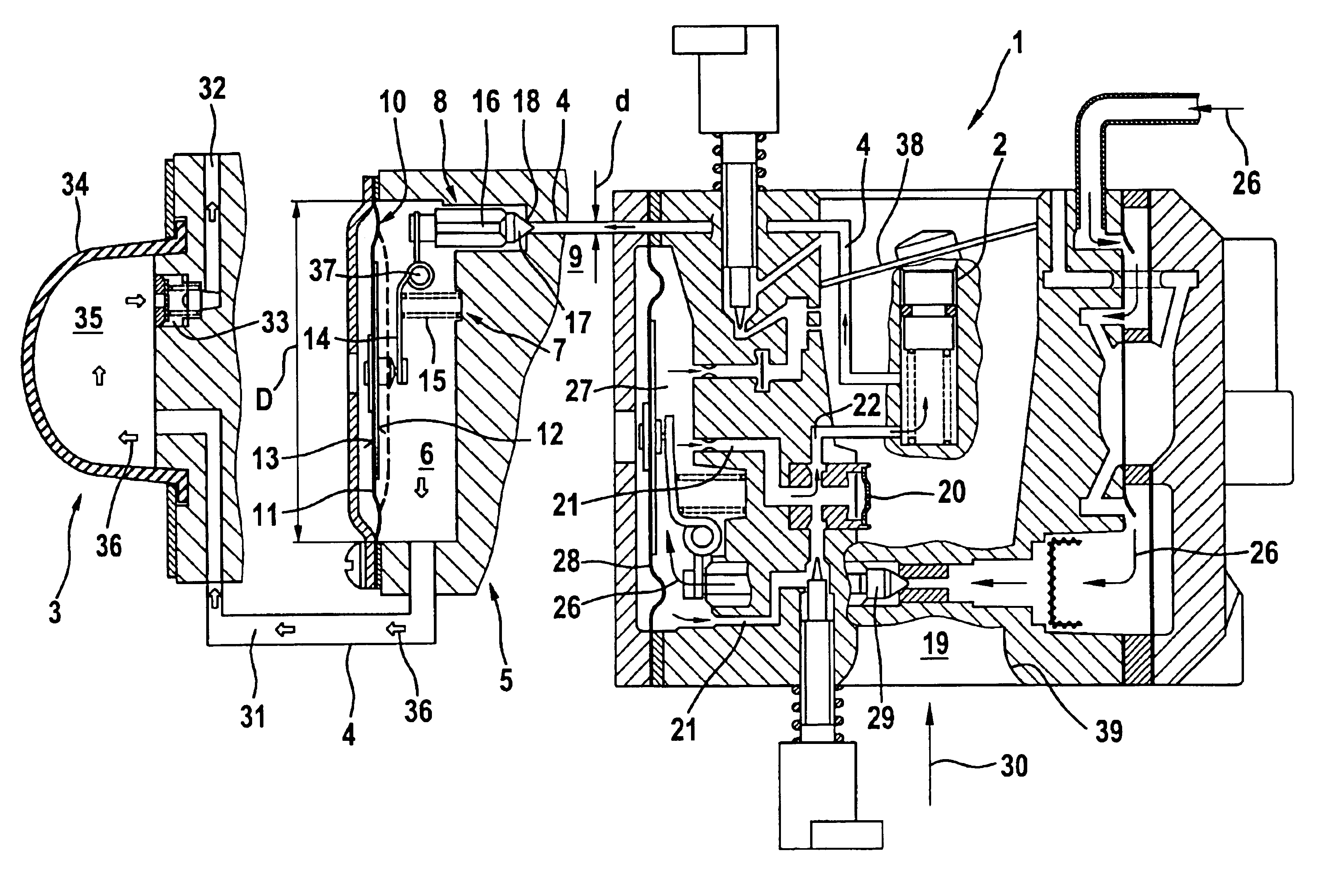
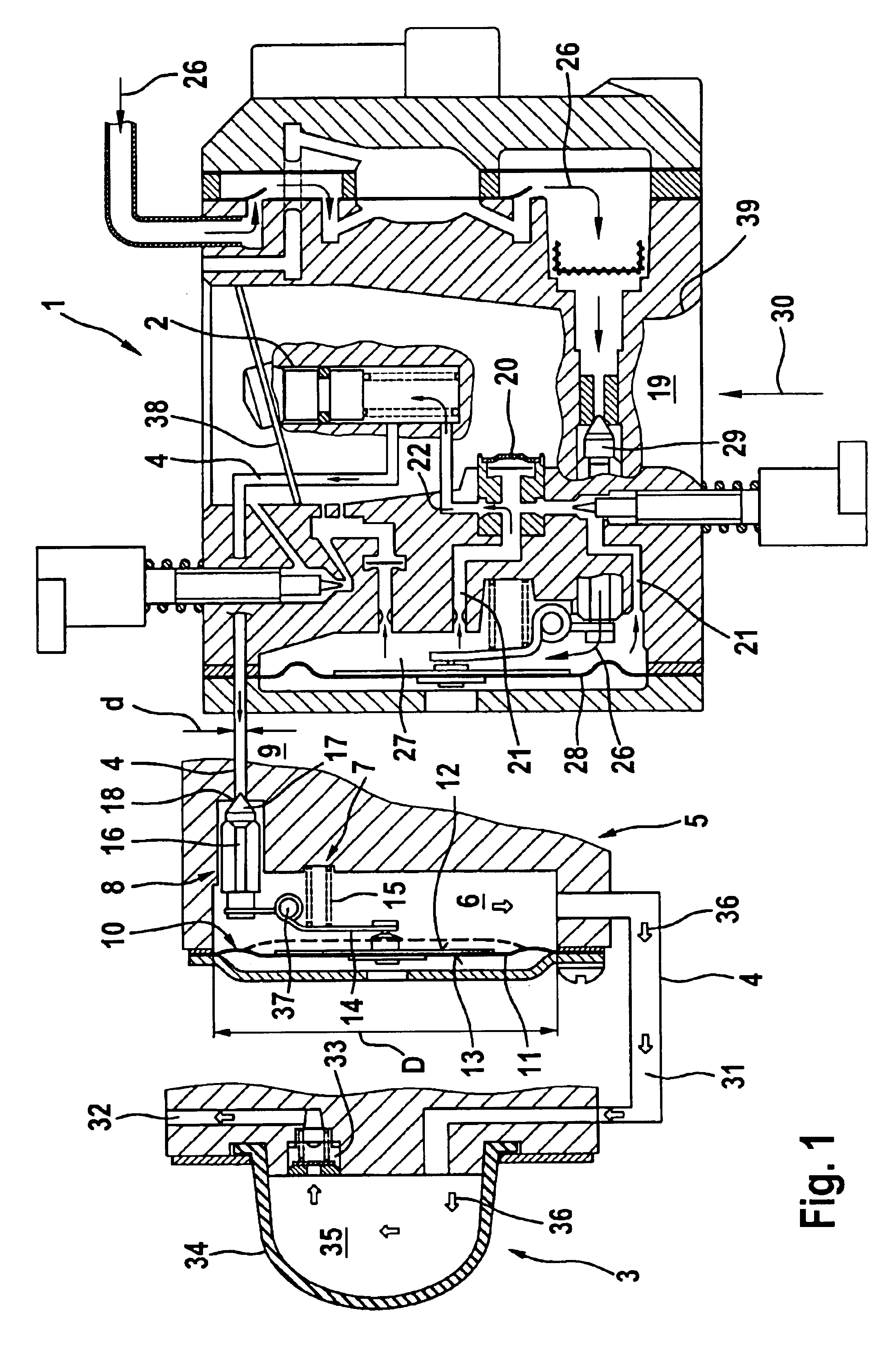
[0019]FIG. 1 shows a schematic section view of a carburetor 1 for an internal combustion engine (not shown) of a portable handheld work apparatus. The carburetor 1 includes an intake channel 19 through which there is a flow in the direction of arrow 30 during operation of the engine. The flow cross section of the intake channel 19 is adjustable by means of a pivotable throttle flap 38 for preselecting a desired power.

[0020]An underpressure forms in a narrowed venturi section 39 when there is a flow through the intake channel 19. Fuel is drawn through a main outlet nozzle 20 because of this underpressure and, with the air flow 30, an air / fuel mixture is prepared for supplying the engine.

[0021]The fuel is drawn by suction in the direction of arrows 26 from a tank (not shown). A control chamber 27 is provided which is delimited by a control membrane 28. Depending upon the pressure in the control chamber 27 and the deflection of the control membrane 28 associated therewith, a valve 29 c...


PUM

PropertyMeasurementUnit
pressureaaaaaaaaaa
acceleration performanceaaaaaaaaaa
suction forcesaaaaaaaaaa

Abstract

The invention relates to a carburetor arrangement of a portable handheld work apparatus and includes a carburetor (1), an accelerator pump (2) and a venting pump (3). The venting pump (3) acts on the accelerator pump (2) via a venting line (4). A check valve (5) is mounted in the venting line (4) in such a manner that its outlet end (6) is directed in the direction of the venting pump (3). A pretensioning device (7) is provided which holds a valve body (8) of the check valve (5) closed below a selected difference pressure between the outflow end (6) and an opposite-lying inflow end (9). A support device (10) which acts on the valve body (8) and is actuable, at one end, by pressure at the outflow end (6) without considering pressure at the other end (9) or by pressure on the inflow end (9) without considering the pressure on the other end (6).

Description

CROSS REFERENCE TO RELATED APPLICATION[0001]This application claims priority of German patent application no. 103 41 600.5, filed Sep. 10, 2003, the entire content of which is incorporated herein by reference.BACKGROUND OF THE INVENTION[0002]Portable handheld work apparatus such as motor-driven chain saws, brushcutters, suction / blower apparatus or the like have an internal combustion engine as a drive motor. These apparatus have a carburetor arrangement for supplying the engine with an air / fuel mixture. The carburetor arrangement must ensure a good starting performance and also a good acceleration performance of the engine.[0003]An adequately rich air / fuel mixture is required during a sudden acceleration operation. This air / fuel mixture cannot reliably be adjusted exclusively via the suction forces acting on the fuel nozzle in the intake channel. So-called accelerator pumps are known for making available additional fuel quantities when pulling on the throttle. These accelerator pump...

Claims


Application Information

Patent Timeline
Patent Type & Authority Patents(United States)
IPC IPC(8): F02M7/08F02M7/00
CPCF02M7/08
Inventor KNAUS, KONRADHAGELE, ANDREAS
Owner ANDREAS STIHL AG & CO KG
Why Eureka
Try Eureka