Matrix element precharge voltage adjusting apparatus and method

a technology of pre-charge voltage and adjusting apparatus, which is applied in the direction of electric variable regulation, process and machine control, instruments, etc., can solve the problems of large exposure errors, failure to provide any means to compensate for such variations, and the parasitic capacitance of the columns may be a severe limitation on drive accuracy

Inactive Publication Date: 2005-09-13
CLARE MICRONIX INTEGRATED SYST
View PDF39 Cites 256 Cited by
  • Summary
  • Abstract
  • Description
  • Claims
  • Application Information

AI Technical Summary

Problems solved by technology

Low slew rates may cause large exposure errors for short exposure periods.
Thus, for practical implementations of display drivers using the prior art scheme, the parasitic capacitance of the columns may be a severe limitation on drive accuracy.
In many applications the voltage required for display elements at a given current will vary as a function of display manufacturing variations, display aging and ambient temperature, and Okuda also fails to provide any means to compensate for such variation.

Method used


Image

  • Matrix element precharge voltage adjusting apparatus and method
  • Matrix element precharge voltage adjusting apparatus and method
  • Matrix element precharge voltage adjusting apparatus and method

Examples


Embodiment Construction

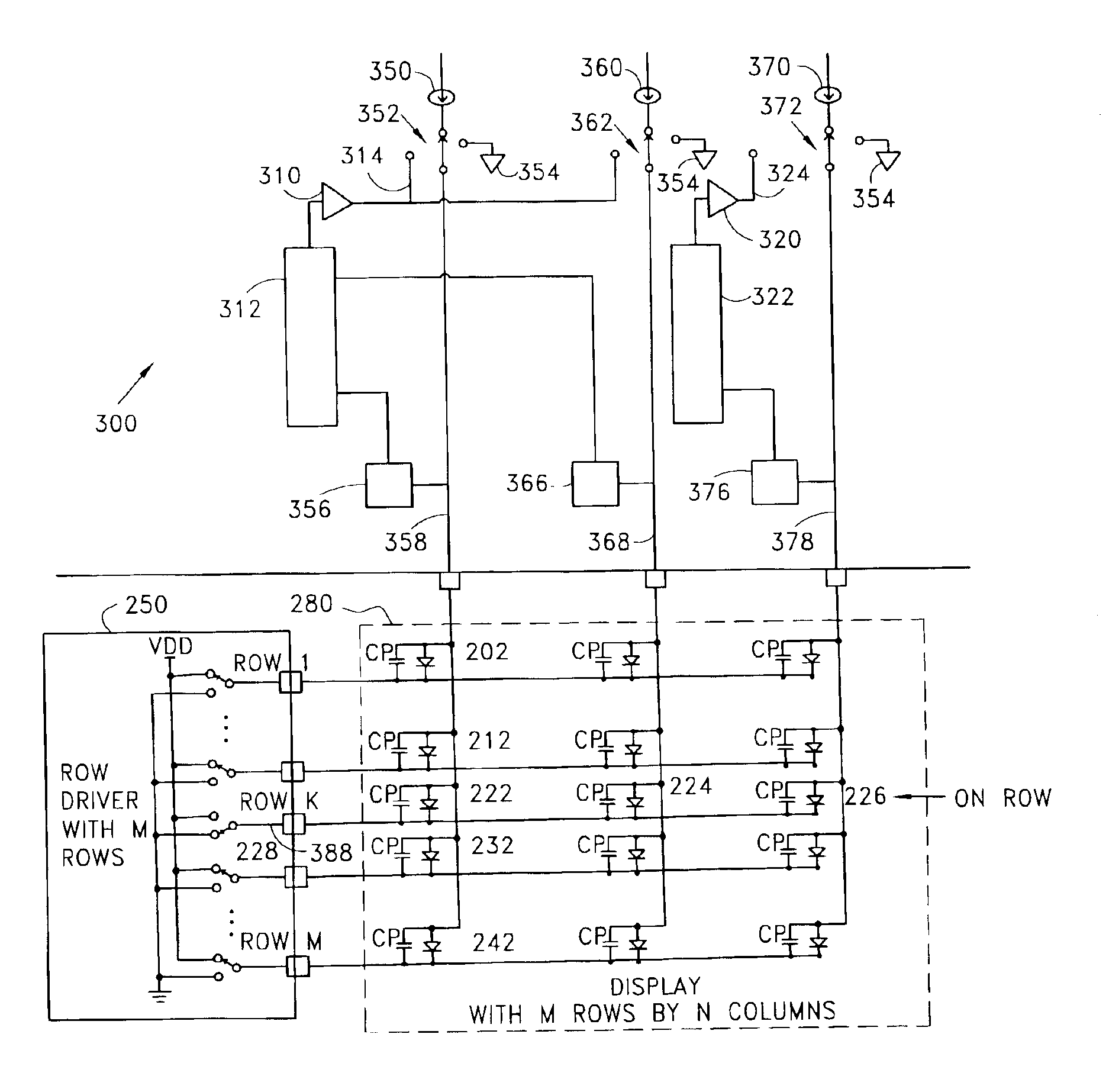
[0068]The embodiments described below overcome obstacles to the accurate generation of a desired amount of light emission from an LED display, particularly in view of impediments which are rather pronounced in OLEDs, such as relatively high parasitic capacitances, and forward voltages which vary with time and temperature. However, the invention is more general than the embodiments which are explicitly described, and is not to be limited by the specific embodiments but rather is defined by the appended claims. In particular, the invention may be applied to enhance the accuracy of current delivered to any matrix of current-driven devices.

Normal Display Drive

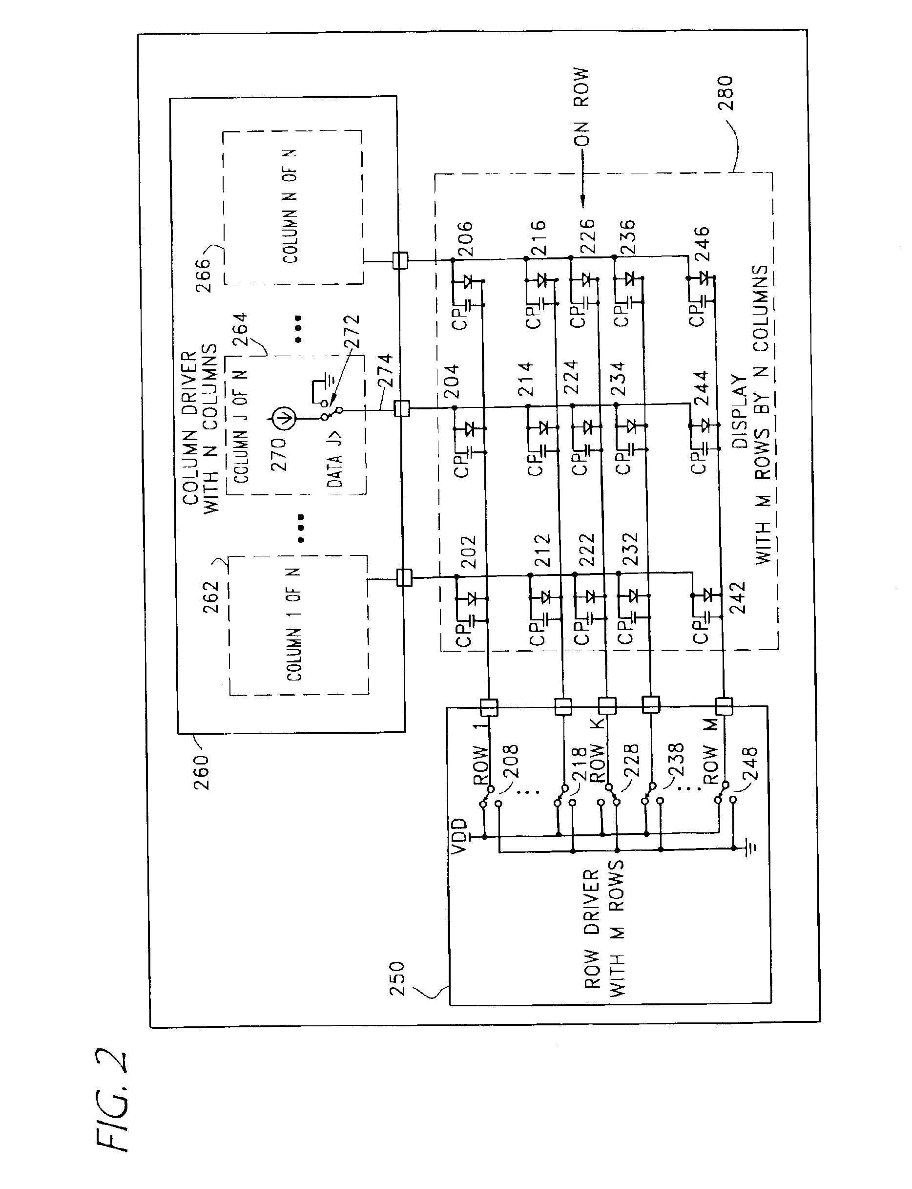
[0069]Referring again to FIG. 2, further details are shown of a passive current-device matrix and drive system as used with embodiments described herein. Current sources such as the current source 270 are typically used to drive a predetermined current through a selected pixel element such as the element 224. However, applied curre...


PUM

PropertyMeasurementUnit
parasitic capacitanceaaaaaaaaaa

Abstract

An apparatus for establishing and applying a voltage to precharge current-driven elements in a matrix. During ordinary scan cycles, a conduction voltage is sensed while the elements conduct a selected current. One or more such sensed conduction voltages are combined to provide a basis for a precharge voltage. Conduction and transient errors are determined, and are compensated for by offsetting the final precharge voltage from the conduction voltage basis. The final precharge voltage is provided to one or more columns during a precharge period of the scan cycle.

Description

RELATED APPLICATIONS[0001]This application claims priority to, and hereby incorporates by reference, the following patent applications:[0002]U.S. Provisional Patent Application No. 60 / 342,637, filed on Oct. 19, 2001, entitled PROPORTIONAL PLUS INTEGRAL LOOP COMPENSATION USING A HYBRID OF SWITCHED CAPACITOR AND LINEAR AMPLIFIERS;[0003]U.S. Provisional Patent Application No. 60 / 343,856, filed on Oct. 19, 2001, entitled CHARGE PUMP ACTIVE GATE DRIVE;[0004]U.S. Provisional Patent Application No. 60 / 343,638, filed on Oct. 19, 2001, entitled CLAMPING METHOD AND APPARATUS FOR SECURING A MINIMUM REFERENCE VOLTAGE IN A VIDEO DISPLAY BOOST REGULATOR;[0005]U.S. Provisional Patent Application No. 60 / 342,582, filed on Oct. 19, 2001, entitled PRECHARGE VOLTAGE ADJUSTING METHOD AND APPARATUS;[0006]U.S. Provisional Patent Application No. 60 / 346,102, filed on Oct. 19, 2001, entitled EXPOSURE TIMING COMPENSATION FOR ROW RESISTANCE;[0007]U.S. Provisional Patent Application No. 60 / 353,753, filed on Oct...

Claims


Application Information

Patent Timeline
Patent Type & Authority Patents(United States)
IPC IPC(8): G09G3/10G09G3/04G09G3/30C22B9/02G01R31/00G05F3/02G09GG09G3/32G09G5/00H02M1/08H02M3/07H03F1/08H03F3/45H03F3/68
CPCG09G3/3216G09G3/3283G09G2310/0248G09G2310/0251G09G2320/0223G09G2320/029G09G2310/0259
Inventor LECHEVALIER, ROBERT
Owner CLARE MICRONIX INTEGRATED SYST
Why Eureka
Try Eureka