Pipe conduit vehicle

a technology for conduits and vehicles, applied in the direction of cleaning hollow objects, cleaning using tools, pipe/joints/fittings, etc., can solve the problems of poor fluid dynamics and substantial technical difficulties

Inactive Publication Date: 2005-09-20
PII PIPETRONIX
View PDF8 Cites 41 Cited by
  • Summary
  • Abstract
  • Description
  • Claims
  • Application Information

AI Technical Summary

Problems solved by technology

These conventional embodiments have the disadvantage of substantial technical difficulty associated with tubes and

Method used


Image

  • Pipe conduit vehicle
  • Pipe conduit vehicle
  • Pipe conduit vehicle

Examples


Embodiment Construction

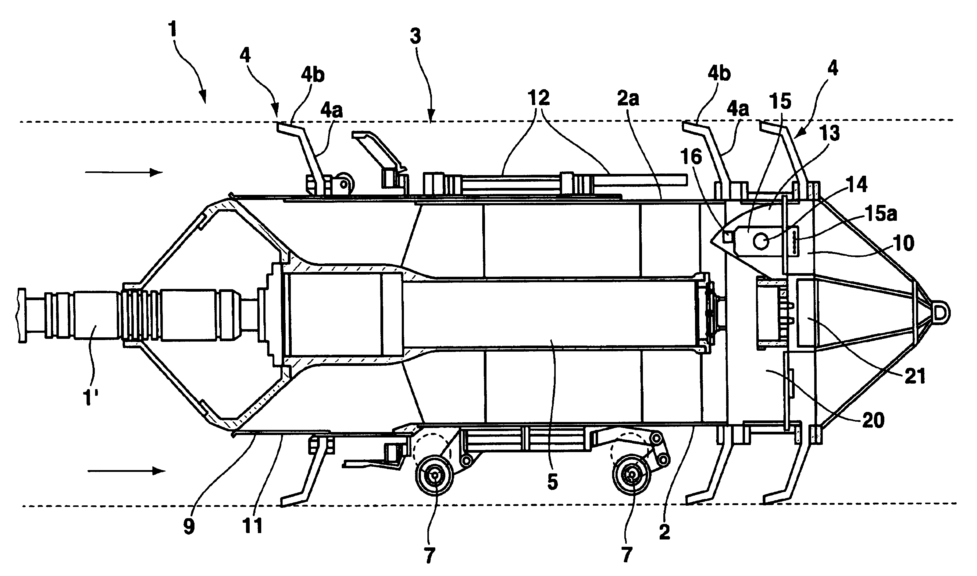
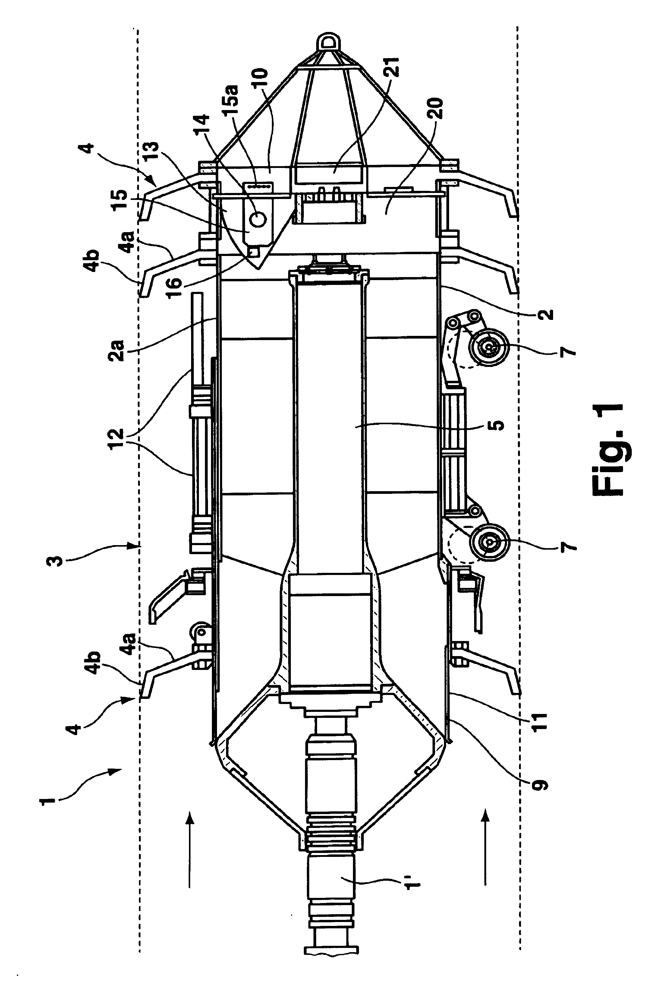
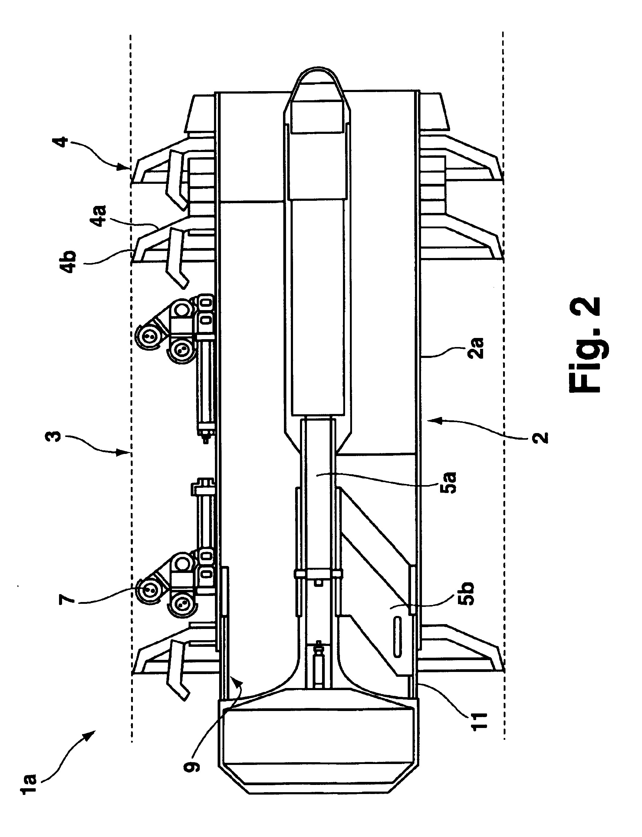
[0029]A pipe conduit vehicle 1 in accordance with the invention comprises a cylindrical housing 2 having an outer wall 2a and ring-shaped sealing collars 4 disposed between the outer wall 2a and a schematically indicated pipe conduit inner wall 3. The pipe conduit vehicle 1 in accordance with the invention can be a pulling module for pulling, via coupling element 1, additional modules of a cleaning or inspection pig. Each ring-shaped sealing collar 4 has a first section 4a tilted towards the rear and a second section 4b which is tilted with respect to the first section 4a and which extends in a backward direction to seat, under pressure, on the inner wall of the pipe conduit. The second section forms a seal at the inner wall of the pipe conduit 3 and therefore guarantees the necessary pressure build-up on the input flow side of the sealing collar 4 for the forward drive. Spring-loaded wheels 7 are disposed on the outer wall 2a of the cylindrical housing 2 between two ring-shaped sea...


PUM


Abstract

A pipe conduit vehicle having a substantially cylindrical housing and with at least one ring-shaped sealing element disposed between the outer side of the housing and the inner wall of the pipe conduit can be moved in the pipe conduit via the transport fluid flow. The pipe conduit vehicle thereby comprises at least one inlet opening and at least one outlet opening which form a bypass through the inner portion of the housing to reduce the pressure differential before and after the pipe conduit vehicle, wherein the at least one inlet opening is disposed on the outer surface of the cylindrical housing.

Description

PIPE CONDUIT VEHICLE[0001]This application claims Paris Convention priority of DE 198 20 290.3 filed May 7, 1998 the complete disclosure of which is hereby incorporated by referenceBACKGROUND OF THE INVENTION[0002]The invention concerns a pipe conduit vehicle which can be moved within the pipe conduit via a transport fluid flow, comprising a housing having an outer surface and with at least one outer ring-shaped sealing element as well with at least one inlet opening and at least one outlet opening on the housing before and behind the sealing element to form a bypass.[0003]Pipe conduit vehicles of this kind, which are designated as pigs, are used for the inspection or cleaning of pipelines which is of primary importance in pipelines in which poisonous or dangerous gases or liquids such as natural gas or liquid oil products are transported.[0004]The above described pipe conduit vehicle can be the cleaning or inspection vehicle itself or can serve as a pulling vehicle or module theref...

Claims


Application Information

Patent Timeline
IPC IPC(8): B08B9/04B08B9/02F16L55/38F16L55/26B08B9/049
CPCB08B9/0551F16L55/38
Inventor RICHTER, THOMASGUNTER, FRANKBREMNER, GEORGE FRANKLYNCOMELLO, CORRY
Owner PII PIPETRONIX
Why Eureka
Try Eureka