Siphon tube of connector adapted to be mounted on reservoir

a technology of connector and siphon tube, which is applied in the directions of bends, liquid transferring devices, transportation and packaging, etc., can solve the problems of adversely affecting any subsequent treatment conducted in the outside facilities

Inactive Publication Date: 2005-09-20
SURPASS IND
View PDF18 Cites 2 Cited by
  • Summary
  • Abstract
  • Description
  • Claims
  • Application Information

AI Technical Summary

Benefits of technology

[0012]The present invention has the above construction. Consequently, in the connector of the present invention adapted to be mounted on the reservoir, since the liquid-inlet opening of the siphon tube is directed normal to the longitudinal axis of the siphon tube, there is substantially no fear th

Problems solved by technology

Further, the slurries thus sucked and transferred to the outside facilities adversely affect any subseq

Method used


Image

  • Siphon tube of connector adapted to be mounted on reservoir
  • Siphon tube of connector adapted to be mounted on reservoir
  • Siphon tube of connector adapted to be mounted on reservoir

Examples


first embodiment

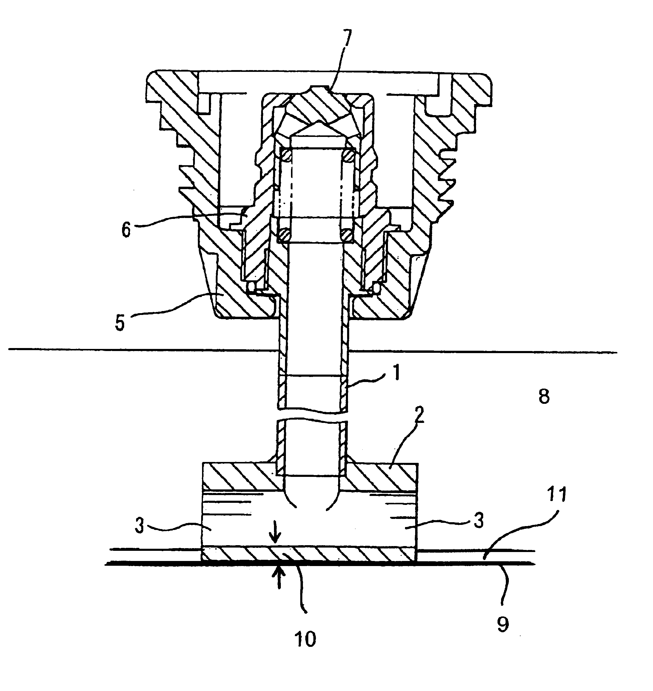
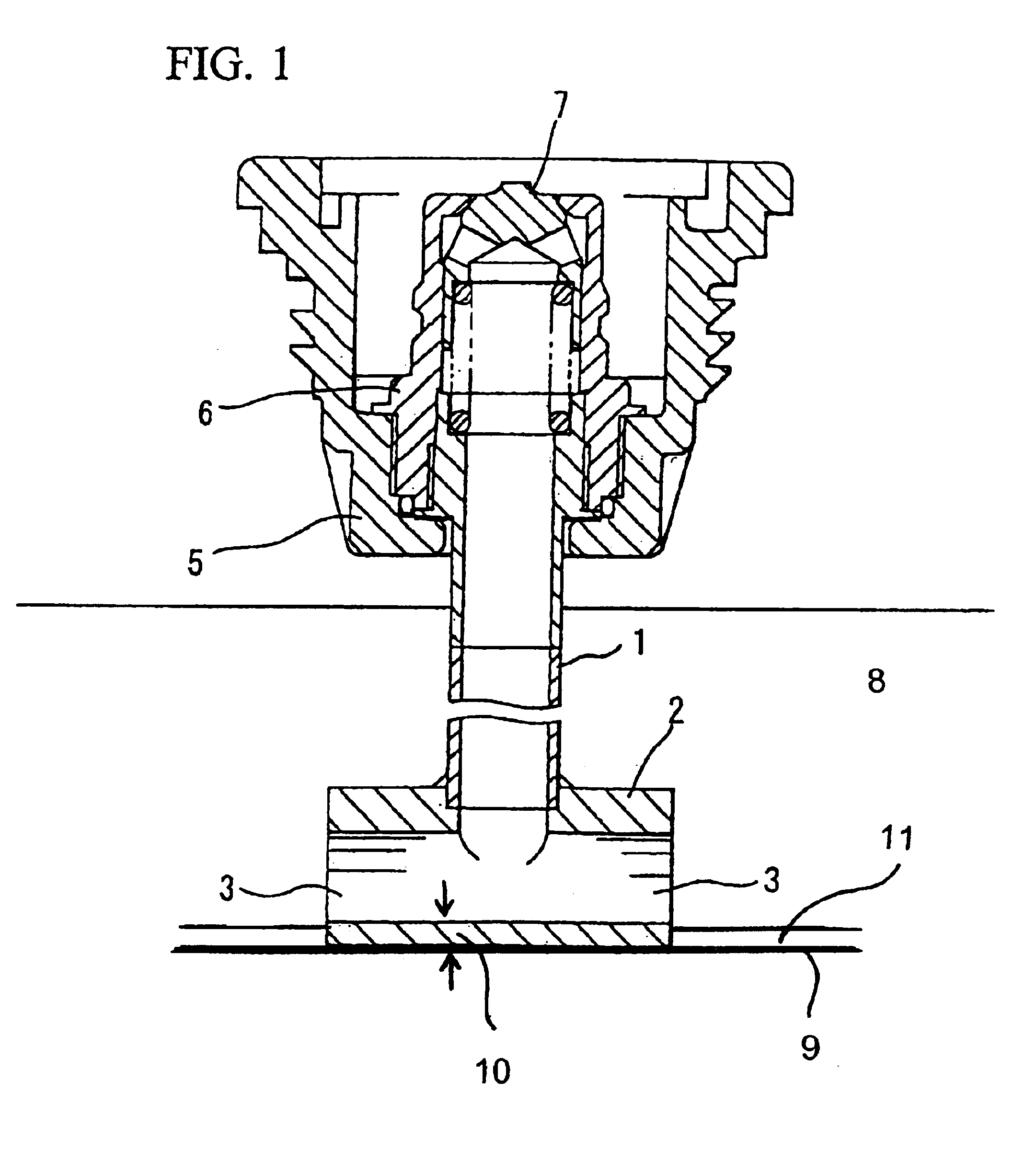
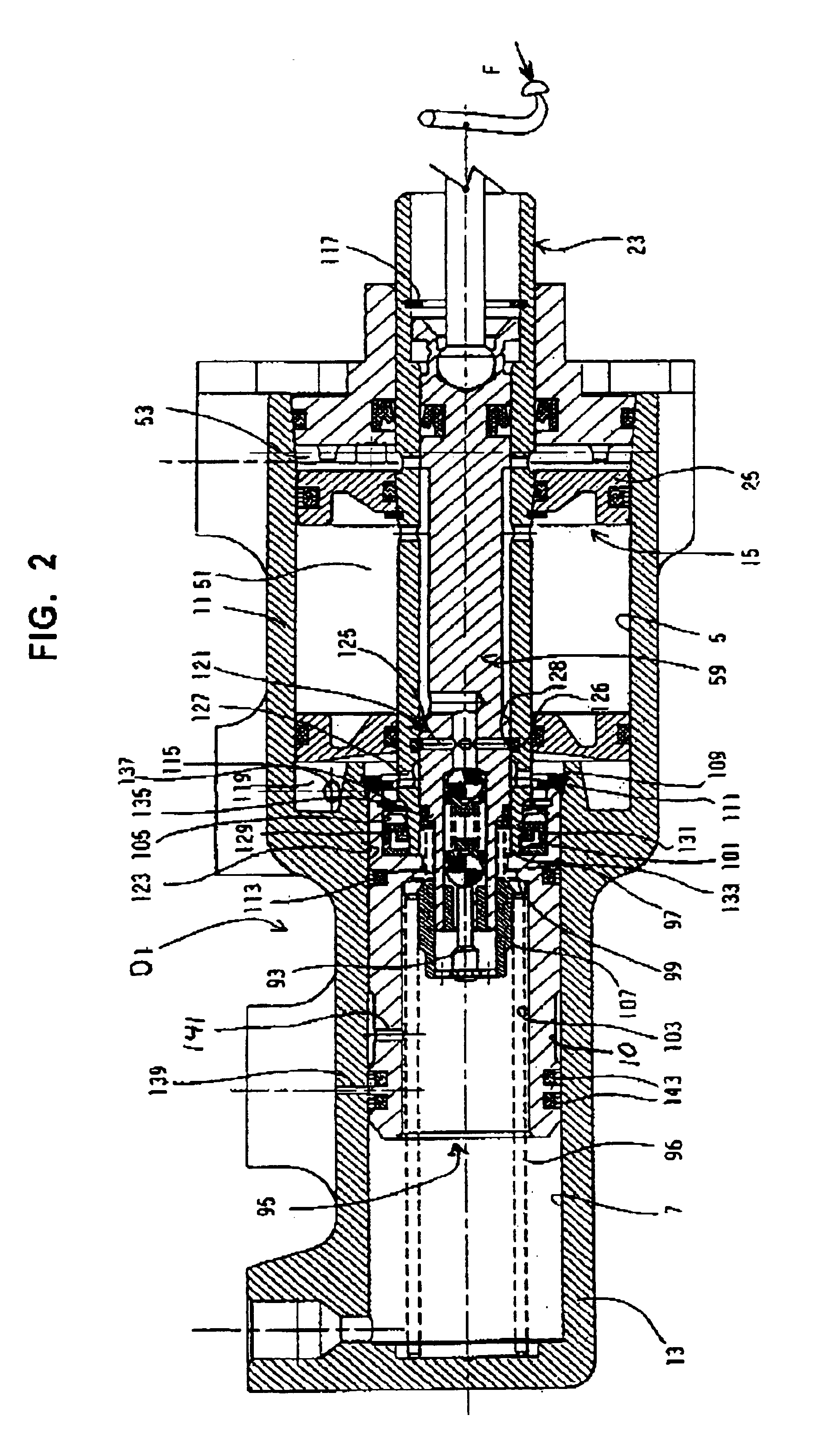
[0021]FIGS. 1 and 2 show a first embodiment of a siphon tube 1 of the present invention. As shown in the drawings, an end portion 2 of the siphon tube 1 assumes an inverted T-shaped form provided with a laterally extending portion which reaches to the vicinity of the bottom or to the bottom of the reservoir as indicated above. The laterally extending portion of the siphon tube 1 is provided with opposite end openings in it opposite ends. Each of the opposite end openings of the end portion 2 serves as a liquid-inlet opening 3. In the first embodiment, the end portion 2 may be integrally formed with a main body of the siphon tube 1. As shown in FIG. 1, in the first embodiment, the end portion 2 and the main body of the siphon tubes 1 are separately formed and thereafter combined with each other using suitable fastening means to form the entire siphon tube 1. It is preferable to have the end portion 2 of the siphon tube 1 be larger in wall thickness than the main body of the siphon tu...

second embodiment

[0023]FIG. 3 shows a second embodiment of the end portion 2 of the siphon tube 1. In the second embodiment, the end portion 2 of the siphon tube 1 is bent to form a curved L-shaped portion provided with a laterally extending portion a front end portion of which forms the liquid-inlet opening 3 directed normal to the longitudinal axis of the siphon tube 1. In this embodiment, the laterally extending portion of the siphon tube 1 may abut against the bottom of the reservoir or may be disposed adjacent to the bottom of the reservoir, and may be large in wall thickness (see the phantom lines shown in FIG. 3).

third embodiment

[0024]FIGS. 4(A) and 4(B) show a third embodiment of the siphon tube 1 of the present invention. In this embodiment, the siphon tube 1 has its lower end portion closed with a closure or cap 4. At least one opening is formed in a circumferential surface of the siphon tube 1 in a position adjacent to an upper surface of the cap 4 to serve as the liquid-inlet opening 3. In this embodiment, the reason why a lower end of the liquid-inlet opening 3 is disposed adjacent to the closure or cap 4 is that: when the lower end of the liquid-inlet opening 3 is spaced apart from the cap 4 so as to be positioned above the cap 4, a deposit space portion is formed-between the lower end of the liquid-inlet opening 3 and an upper surface of the cap 4 to receive the slurries in such a deposit space portion of the reservoir.

[0025]In any one of the above embodiments of the present invention, the liquid-inlet opening 3 through which the liquid contained in the reservoir flows into the siphon tube 1 is slig...


PUM


Abstract

In a siphon tube (1) of a reservoir, even when a front end of tube (1) is in the vicinity of the bottom of the reservoir, there is no fear that slurries are sucked by tube (1) which: reaches the bottom of the reservoir to draw a liquid contained therein out of the reservoir is characterized by a liquid-inlet opening (3) directed normal to a longitudinal axis of tube (1). Tube (1) has its front end formed into: an inverted T-shape provided with opposite end openings in a laterally extending portion thereof, each of which openings forms the liquid-inlet opening (3); or, an L-shaped curved form a front end of which forms an opening directed normal to the longitudinal axis of tube (1); or, is closed with a cap so that an opening is disposed adjacent to an upper surface of the cap to serve as the liquid-inlet opening.

Description

BACKGROUND OF THE INVENTION[0001]1. Field of the Invention[0002]The present invention relates to a siphon tube of a connector adapted to be mounted on a reservoir, and more particularly to a siphon tube of a connector adapted to be mounted on a reservoir, wherein the connector is fixedly mounted on a lid of a liquid reservoir and adapted to be detachably connected with an outside hose for supplying a liquid contained in the reservoir to the outside facilities through both the siphon tube and the outside hose, wherein the liquid comprises various types of industrial chemical agents used in a semiconductor fabrication process, various types of paints, various types of medicines and like liquids.[0003]2. Description of the Related Art[0004]As for a conventional connector adapted to be mounted on a reservoir, the prior art, for example such as Japanese Patent Application Laid-Open No. Hei 11-193894 describes various types of conventional connectors. Of these conventional connectors: a f...

Claims


Application Information

Patent Timeline
IPC IPC(8): B67D5/01B67D5/02B67D7/72B67D7/00B67D7/02F16L43/00H01L21/306
CPCB67D7/007B67D7/0272B67D7/0294
Inventor OZAWA, TOSHIHIKOIMAI, TAKASHI
Owner SURPASS IND
Why Eureka
Try Eureka