Tilt control mechanism for chair

a control mechanism and chair technology, applied in the field of office-type chairs, can solve the problems of increasing the complexity of the chair assembly with respect to required manipulation and assembly time, interfering with occupant comfort, and many of the known mechanisms failing to provide the degree of performance desired

Active Publication Date: 2005-09-20
HAWORTH SPA
View PDF39 Cites 93 Cited by
  • Summary
  • Abstract
  • Description
  • Claims
  • Application Information

AI Technical Summary

Benefits of technology

[0007]More specifically, in the improved chair of this invention, the synchrotilt mechanism employs a seat cradle pivotally supported on the back upright for relative pivoting about an axis typically disposed in the vicinity of the upper surface of the seat, with the relative motion between the seat cradle and back upright being controlled by a tilt control linkage which couples the seat cradle and back upright to the chair base. The tilt control linkage has an elongate control link which at a front end is pivoted to the chair base about a first transverse horizontal axis, which control link at its rearward end has a slide or roller movably engaged within an elongate slot associated with a base leg of the back upright. This control link, where it joins to the back upright, also has a bias or spring arrangement coupled between the seat cradle and the rearward end of the control link to provide a spring-controlled lost motion connection with the seat cradle whereby, during normal rearward tilting of the back upright, the seat cradle also tilts rearwardly but at a lesser rate as permitted by compression of the spring between the control link and the seat cradle. This same spring and the lost motion connection defined thereby also enables the seat cradle to tilt forwardly a limited extent in response to forward leaning of the chair occupant to provide a simple forward tilt function at least when the chair is in the normal upright position.

Problems solved by technology

Most of these mechanisms, however, have caused relative motion between the chair and the seated occupant which has interfered with occupant comfort.
While locating the relative tilt axis between the seat and back at the occupant's hip axis is believed to provide improved performance, particularly with respect to minimizing the relative sliding motion between the seated occupant and the seat / back, nevertheless many of these known mechanisms still fail to provide the degree of performance desired, particularly with respect to the desired comfort and ease of movement (often referred to as “ride”) associated with tilting of the chair.
While the aforementioned chair provides desirable performance and seating comfort, nevertheless it has been observed that the synchrotilt mechanism and the tilt control linkage associated therewith require a significant number of parts as well as pivotal connections, which in turn increases the complexity of the chair assembly with respect to required manipulations and assembly time.
This linkage also is more space-consuming, particularly in view of the limited available space, and this additionally increases the complexities associated with assembly of the chair.

Method used


Image

  • Tilt control mechanism for chair
  • Tilt control mechanism for chair
  • Tilt control mechanism for chair

Examples


Embodiment Construction

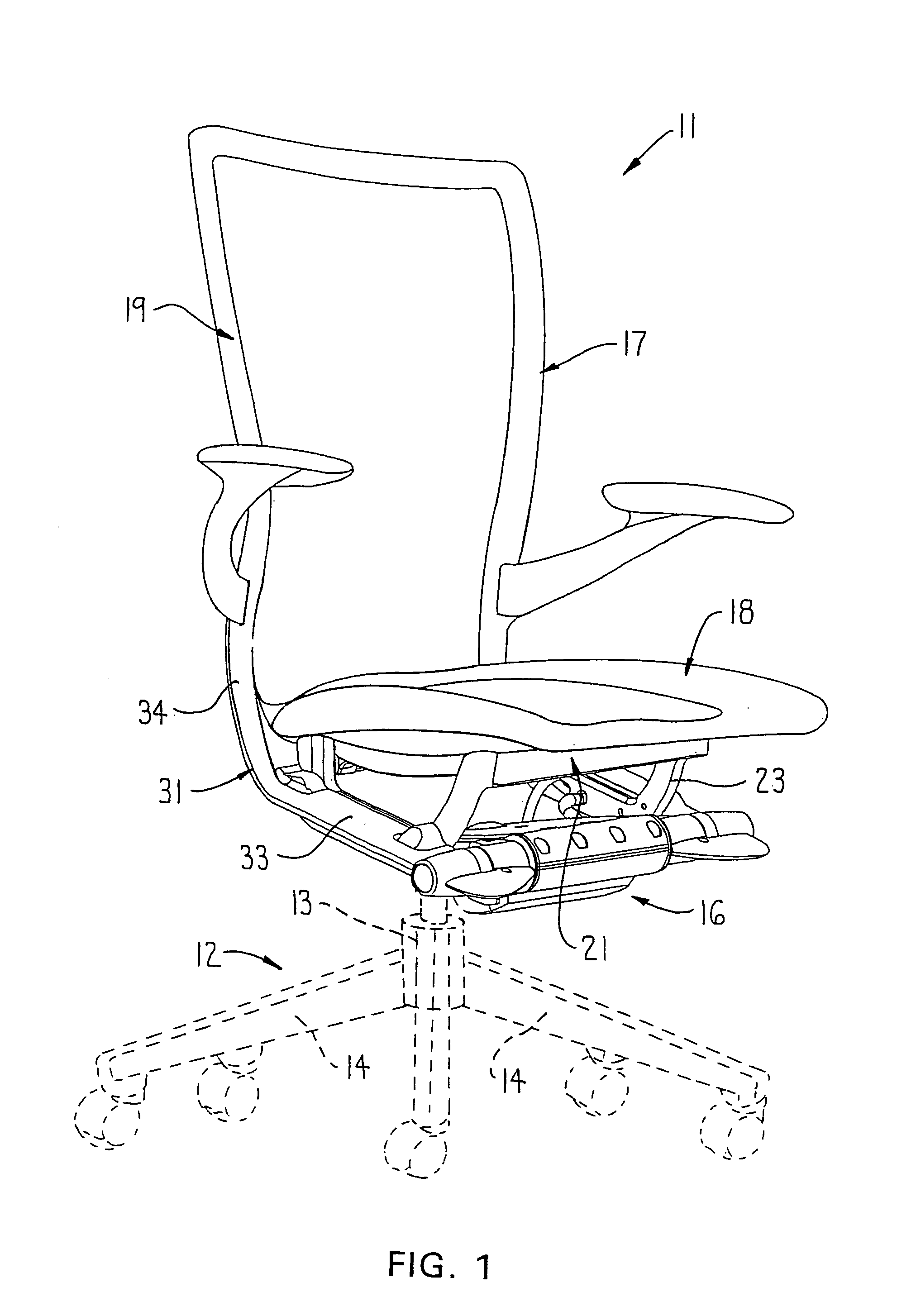
[0024]Referring to FIG. 1, there is illustrated a chair 11 which incorporates therein the improved synchrotilt control according to the present invention. The chair 11 includes a base 12 provided with a plurality of legs 14 which radiate outwardly and are provided with casters for rolling support on a floor. The base 12, centrally thereof, has a height-adjustable pedestal 13 which projects upwardly and, at the upper end thereof, couples to a chair control 16, the latter in turn providing support for an L-shaped seat-back arrangement 17 which includes a seat assembly 18 and a back assembly 19.

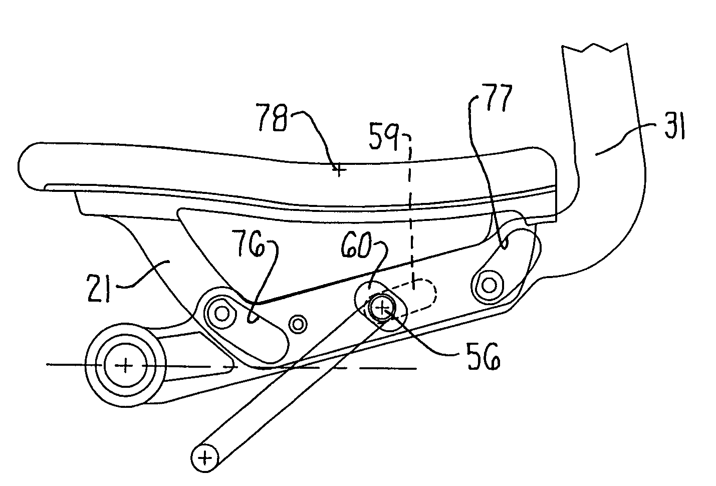
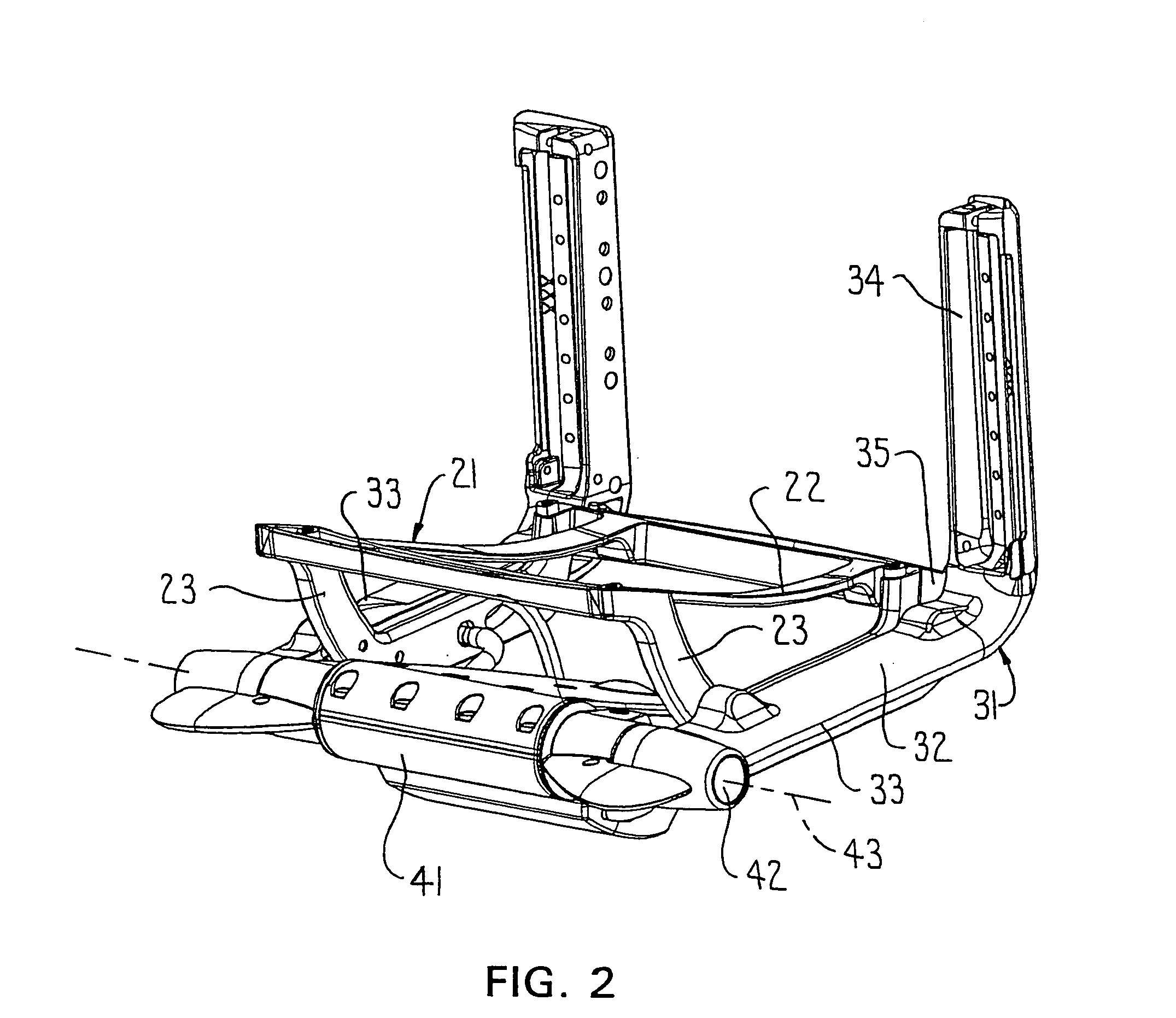
[0025]The seat assembly 18 includes a rigid seat frame or cradle 21 defined by a generally rectangular ring-shaped top frame 22 which, adjacent opposite sides, is provided with generally parallel side frame elements 23. The elements 23 are generally U-shaped and protrude downwardly, with upper ends of the legs being rigidly joined adjacent the front and rear corners of the top frame 22.

[0026]The...


PUM


Abstract

A chair back is supported on a rigid upright coupled to a horizontal tilt shaft disposed under the front of the chair seat and supported on a control housing fixed to a pedestal. A tension mechanism urges the upright into an upright position. The chair seat is movably supported on the upright by an arrangement which permits the seat to pivot about a transverse horizontal axis positioned adjacent the upper surface of the seat. A control link is pivoted at one end to the control housing, and the other end has lost-motion pivotal connections to the seat frame and the upright. The lost-motion pivotal connection to the seat frame including a spring cooperating between the upright and the seat frame to allow the seat to move relative to the upright.

Description

FIELD OF THE INVENTION[0001]This invention relates to an office-type chair, and more specifically relates to an improved synchrotilt mechanism coupled to the seat and back of the chair for providing improved seating comfort.BACKGROUND OF THE INVENTION[0002]Office chairs conventionally provide some type of rearward tilting movement. In its simplest variations, the rear tilting involves solely the back, or the seat and back as a unitary construction. To provide improved and more desirable tilting movement and seating comfort, however, many office-type chairs employ a synchrotilt mechanism coupled between the chair base and the seat-back assembly, for permitting the seat and back to simultaneously tilt at different rates, with the tilt rate and maximum tilt angle of the back typically being about twice the tilt rate and maximum tilt angle of the seat.[0003]Chairs employing synchrotilt mechanisms for permitting simultaneous but relative tilting of the seat and back are well known, and n...

Claims


Application Information

Patent Timeline
Patent Type & Authority Patents(United States)
IPC IPC(8): A47C1/024A47C1/031A47C1/022A47C1/032
CPCA47C1/03255A47C1/03261A47C1/03266A47C1/03294A47C1/03279A47C1/03277
Inventor FOOKES, TIMROSE, JASON M.
Owner HAWORTH SPA
Why Eureka
Try Eureka