Method and apparatus for coil-less magnetoelectric magnetic flux switching for permanent magnets

a permanent magnet and coilless technology, applied in the field of permanent magnet magnet magnetic flux switching, can solve the problems of ineffective use of permanent magnet powered motors, no practical or competitive solution, nothing which suggests how to make effective use of me materials in the context of the design of permanent magnet motors, etc., and achieve the effect of improving the magnetic flux characteristics of the completed constru

Inactive Publication Date: 2005-09-20
PEDERSEN BRAD D
View PDF3 Cites 30 Cited by
  • Summary
  • Abstract
  • Description
  • Claims
  • Application Information

AI Technical Summary

Benefits of technology

[0015]In a preferred embodiment, the coil-less ME magnetic flux switches are implemented as a liquid crystal ME material that is electronically controllable. In an alternate embodiment, the ME material may be physically or optically controllable. Preferably, the ME material is processed onto a desired surface of the magnetic flux conductor or permanent magnet by thin film deposition, sputtering, or other thin film processing techniques. Alternatively, the ME material may be positioned physically interposed between the desired surfaces of the magnetic flux conductors or permanent magnets. In one embodiment, an index matching coating material may be interposed between the ME material and the desired surface of the magnetic flux conductors or permanent magnets to improve the magnetic flux characteristics of the completed construct. In another embodiment, a magnetic insulator material, such as MU metal can be used to house an entire magnetic flux switching construct to prevent external magnetic fields or may be used to magnetically isolate selected portions of a magnetic flux switching construct.

Problems solved by technology

For numerous reasons, such permanent magnet powered motors have not been practical or competitive when compared to conventional electrical motors powered by electromagnetic fields.
While many of the properties of ME materials are understood and there are numerous applications for the use of such liquid crystal materials, there is nothing which suggests how to make effective use of ME materials in the context of the design of permanent magnet motors and the like.

Method used


Image

  • Method and apparatus for coil-less magnetoelectric magnetic flux switching for permanent magnets
  • Method and apparatus for coil-less magnetoelectric magnetic flux switching for permanent magnets
  • Method and apparatus for coil-less magnetoelectric magnetic flux switching for permanent magnets

Examples


Embodiment Construction

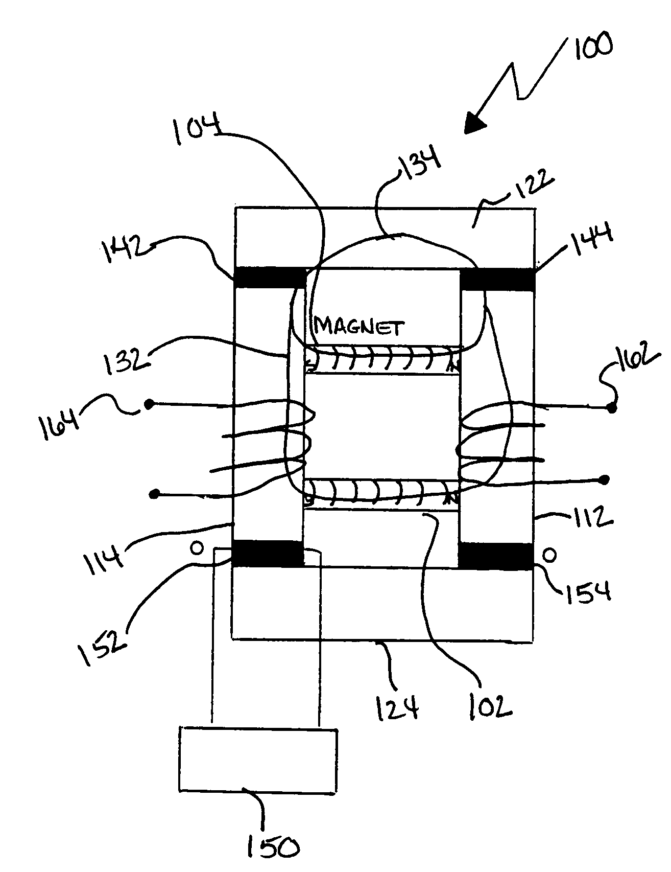
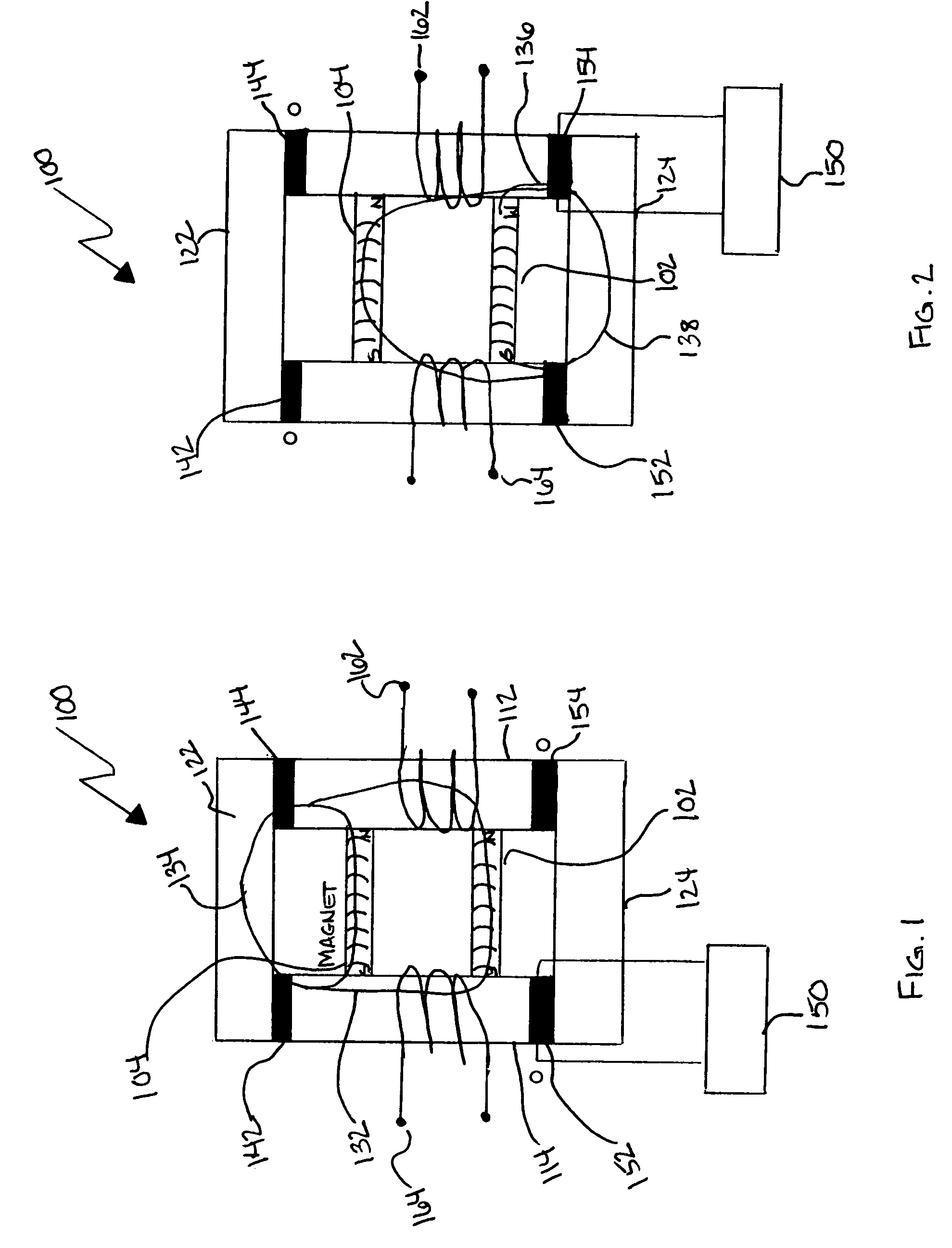
[0028]Referring to FIGS. 1 and 2, a first embodiment of the of a magnetic flux switching construct 100 in accordance with the present invention will be described. A pair of permanent magnets 102, 104 are similarly oriented with each north pole (N) operably adjacent a first magnetic flux conductor 112 and each south pole (S) operably adjacent a second magnetic flux conductor 114. Preferably, the permanent magnets 102, 104 are high strength ceramic or rare-earth permanent magnets such as neodidium, although any material capable of being magnetized and retaining that magnetization for a period of time sufficient for the intended use of the construct 100 could be used. Preferably, the magnetic flux conductors 112, 114 are low loss magnetic flux laminate materials, such as hyperco or an MD grade metal, although any iron, steel or ferrous alloy could be used provided that the magnetic flux loss of such material is within the design parameters of the strength of magnetic flux to be switche...


PUM

PropertyMeasurementUnit
switching frequenciesaaaaaaaaaa
switching magnetic fluxaaaaaaaaaa
magnetic fluxaaaaaaaaaa

Abstract

Methods and apparatus that employ a coil-less magnetoelectric flux switch arrangement to repeatedly switch magnetic flux from at least one permanent magnet for the purposes of generating motive force and / or electrical energy.

Description

FIELD OF THE INVENTION[0001]The present invention relates generally to magnetic fields from permanent magnets and the control of such magnetic fields for use in motors, generators and the like. More particularly, the present invention relates to methods and apparatus that employ a coil-less magnetoelectric (ME) magnetic flux switching construct to repeatedly switch magnetic flux from at least one permanent magnet for the purposes of generating motive force and / or electrical energy.BACKGROUND OF THE INVENTION[0002]The basic electromechanical processes involved in motors and generators are well-known. Mechanical power is produced (in the case of a motor) or electrical energy is generated (in the case of a generator) by the interaction of the electromagnetic forces between the rotor and stator. While almost all conventional motors utilize electromagnetic forces produced by running current through a series of windings in the form of coils of wire to generate the electromagnetic field th...

Claims


Application Information

Patent Timeline
Patent Type & Authority Patents(United States)
IPC IPC(8): H01F21/02H01F21/08H01F3/10H01F7/02
CPCH02K19/02H02K19/10H02K21/12H02K21/26H02K21/44H02K41/03H02K57/006H01F3/10H01F7/0205H01F2003/103H02K99/20
Inventor PEDERSEN, BRAD, D.
Owner PEDERSEN BRAD D
Why Eureka
Try Eureka