
Detachable remote controller for an electronic entertainment device and a method for using the same

a technology of electronic entertainment devices and remote controllers, which is applied in the direction of electric controllers, ignition automatic control, instruments, etc., can solve the problems of inefficiency in creating redundant control function hardware, limited use of remote controllers that have been included with a specific electronic device, and adding cost to the electronic devi

Inactive Publication Date: 2005-09-20
UNIVERSAL ELECTRONICS INC
View PDF3 Cites 116 Cited by
  • Summary
  • Abstract
  • Description
  • Claims
  • Application Information

AI Technical Summary

Benefits of technology

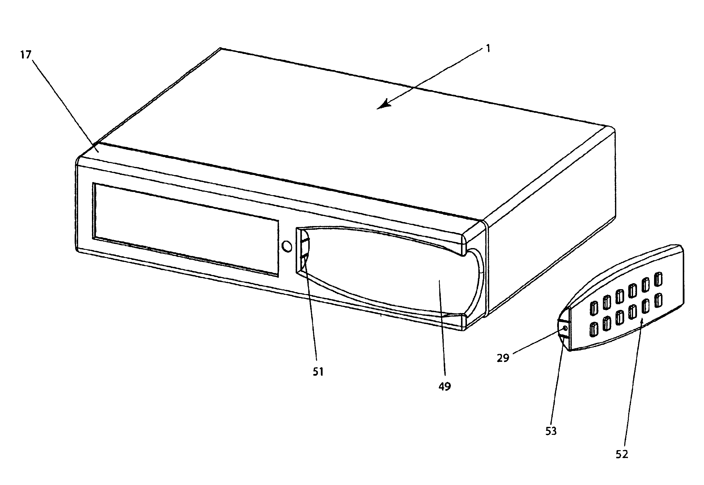
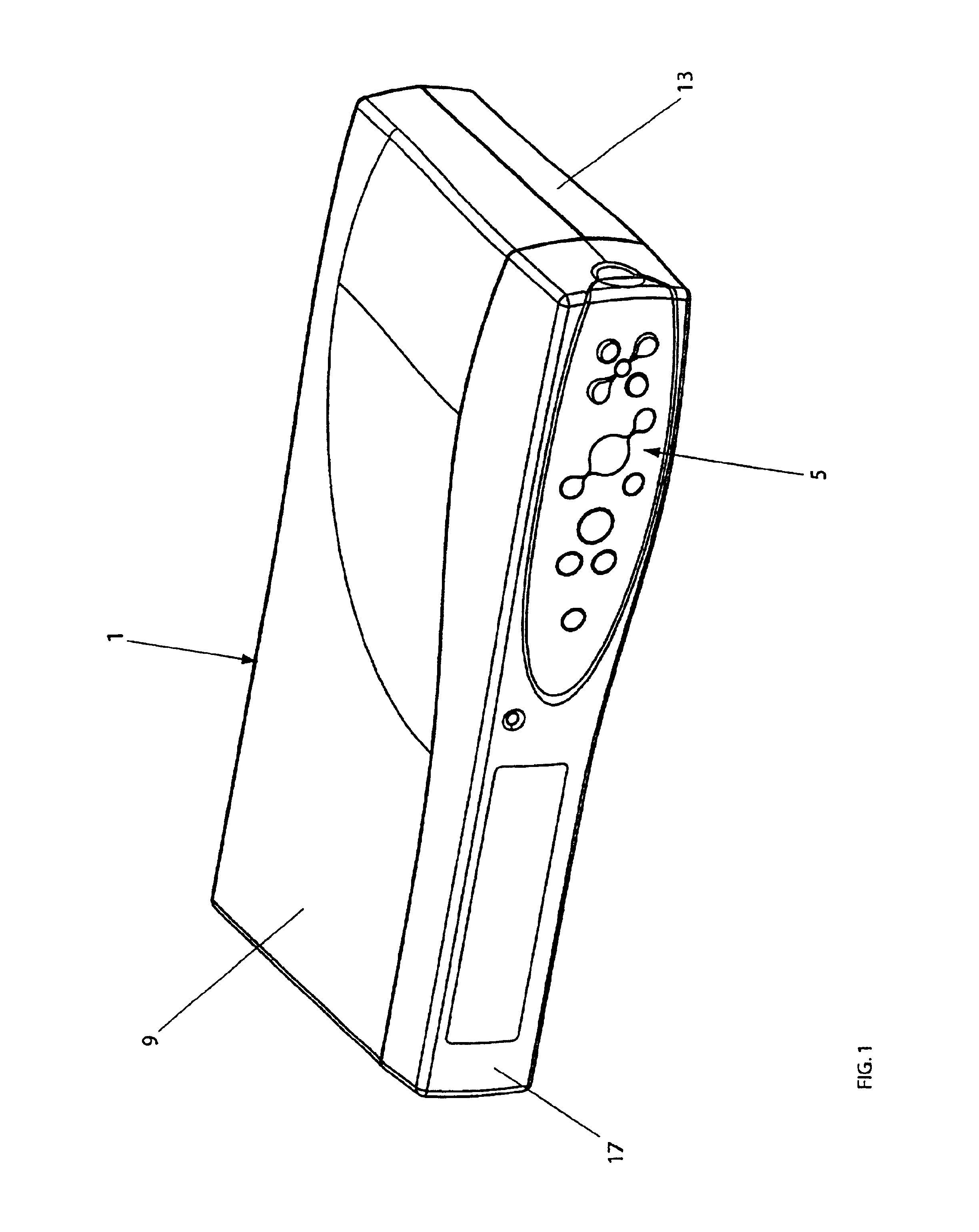
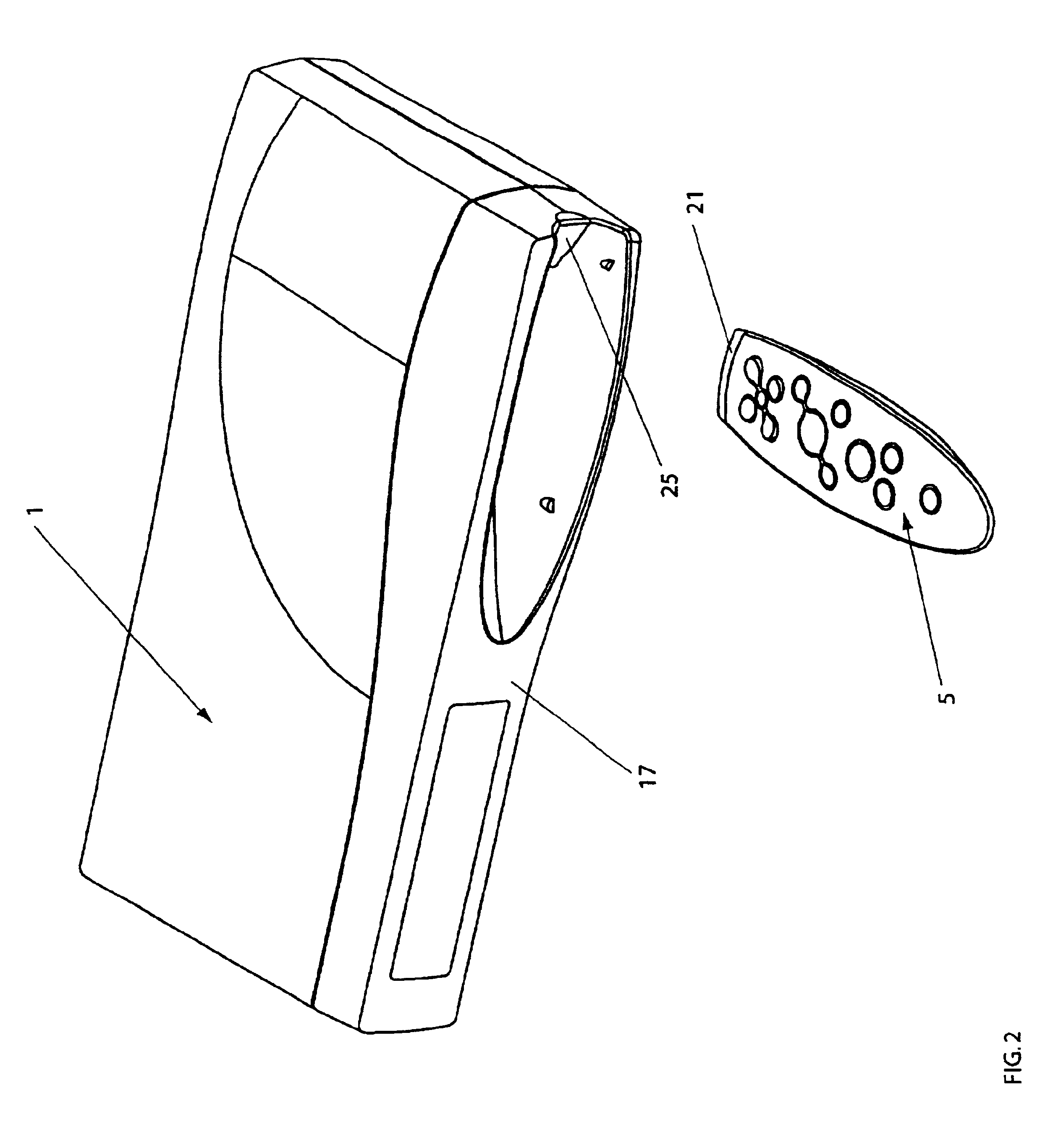
"The patent describes a detachable remote controller for an electronic entertainment device. The remote controller has two infrared transmitters: one is located inside the controller and aligns with a light pipe in the device, and the other is at the end of the controller. When the controller is connected to the device, both infrared transmitters work to send signals. When the controller is not connected, the second infrared transmitter sends signals to the device. The technical effect of this design is that the remote controller can be easily attached and detached from the device, and the signals can be sent even when the controller is not connected."

Problems solved by technology

These remote controllers often include a completely redundant set of controls and interface elements that are included on the main housing of these devices.
Therefore, in many situations, the use of the remote controllers that have been included with a specific electronic device is limited.
There is also inefficiency in creating redundant control function hardware and computer processing sub-systems, such as keypad scanning sub-systems, which adds cost to the electronic device.

Method used


Image

  • Detachable remote controller for an electronic entertainment device and a method for using the same
  • Detachable remote controller for an electronic entertainment device and a method for using the same
  • Detachable remote controller for an electronic entertainment device and a method for using the same

Examples


Embodiment Construction

[0022]A detachable remote controller for an electronic entertainment device and a method for using the same are described. In the following description, for purposes of explanation, numerous specific details are set forth in order to provide a thorough understanding of the present invention. It will be apparent, however, to one skilled in the art that the present invention can be practiced without these specific details. In other instances, well-known structures and devices are shown in block diagram form in order to avoid obscuring the present invention.

[0023]The detachable remote controller relates to a variety of electronic devices that typically include rectilinear enclosures consisting of plastic or sheet metal components. The electronic device 1 in one embodiment is shown as a generic shape with an LED display on the front. Examples of electronic devices for which the detachable remote controller can implemented are multiple disk CD-ROM changers, stereo receivers, VCRs, cable ...


PUM


Abstract

A detachable remote controller for an electronic entertainment device and a method for using the same are provided. The detachable remote controller includes a first infrared transmitter and a second infrared transmitter. The first infrared transmitter transmits signals to the electronic device while the detachable remote controller is coupled with the entertainment device. The remote controller is shaped in such a way to be docked within a cavity and flush with one surface of the entertainment device. The first infrared transmitter is aligned in the cavity such that the first infrared transmitter transmits signals to a light pipe embedded within the entertainment device. The second infrared transmitter is located at one end of the detachable remote controller to transmit signals to the entertainment device while the detachable remote controller is not coupled with the entertainment device.

Description

RELATED APPLICATIONS[0001]This application claims the benefit of the filing date of the following U.S. Patent Application:[0002]U.S. Provisional Patent Application No. 60 / 247,259, titled “Detachable Remote Control For Electronic Entertainment Devices”, and filed on Nov. 10, 2000.FIELD OF THE INVENTION[0003]The present invention relates generally to ubiquitous computing devices and, more particularly, to a detachable remote controller.BACKGROUND[0004]The convenience afforded by the use of infra-red (IR) remote controllers to control a wide range of audio-visual (A / V) equipment has made remote controllers ubiquitous. The majority of A / V consumer electronics devices, such as televisions, stereo receivers, CD-ROM changers, analog and digital set-top boxes, and VCRs, are sold with infra-red (IR) remote controllers. These remote controllers often include a completely redundant set of controls and interface elements that are included on the main housing of these devices. Some devices, such...

Claims


Application Information

Patent Timeline
Patent Type & Authority Patents(United States)
IPC IPC(8): G08C23/00G08C23/04
CPCG08C23/04G08C2201/63
Inventor EDWARDS, BRUCEJANIK, CRAIG M.SUMMIT, SCOTT
Owner UNIVERSAL ELECTRONICS INC
Learn More