Solar blackbody waveguide for efficient and effective conversion of solar flux to heat energy

a solar flux and blackbody technology, applied in the direction of heat collector mounting/support, hybrid energy generation, lighting and heating apparatus, etc., can solve the problems of low energy-density of ambient sunlight, large geometry of concentrator assemblies, and large heat-producing capacity of megawatts (mw)

Active Publication Date: 2005-05-31
MECHAM TRAVIS W
View PDF9 Cites 84 Cited by
  • Summary
  • Abstract
  • Description
  • Claims
  • Application Information

AI Technical Summary

Problems solved by technology

Production of electricity in the Megawatt (MW) range requires enormous amounts of heat.
Assembling enough energy from weak solar energy in a single location to power a generator in this range remains the defining technical challenge of this form of solar energy.
The low energy-density of ambient sunlight requires that the geometry of concentrator assemblies be very large.
The second method transmits large quantities of solar energy over large distances in a nearly lossless manner to a single “receiver” point.
However, each system has introduced its own technical complications, thermal losses, and inefficiencies as described briefly below.
This system has high thermal losses due to the fact that the oil-filled pipe at the center of the concentrator trough is not insulated and re-radiates the accumulated heat back into space.
Also, not all the solar energy incident on the pipe containing the heat transfer fluid is absorbed by the fluid.
In addition, use of a heat exchanger in the steam generator loop increases the overall inefficiencies of the system.
These components combine to limit the gains that can be acquired from magnitude-of-scale operation.
In addition, there are other limitations for these implementations since these systems do not track the sun from east to west, although they do track the seasonal inclination angle.
This system also has high thermal losses.
Additionally, use of a heat exchanger in the steam generator loop increases the overall inefficiencies of the system.
These thermal considerations combine to limit the gains that can be acquired from magnitude-of-scale construction and lower the overall thermal efficiency.
In addition, there are other limitations for power towers since self-shadowing of the heliostats keeps them from providing power over the entire day.
However, these dish engine systems do not overcome the same basic drawback of the other technologies, i.e. high thermal losses with the receiver suspended in the air with limited insulation and resultant with re-radiation of accumulated heat back into space.
The structures required to support the dish and engine can become massive and expensive to construct.
However, the means for doing this as demonstrated in the art is not entirely physically realizable.
In this process, the need for accumulation of energy is recognized, but the physical mechanism for making it happen on a large scale is sketchy.
Although this patent contains some interesting abstract concepts, it does not obtain a complete solution when scaled up for actual power production levels.
An inherent difficultly that this technology fails to overcome is the transmission losses associated with moving highly concentrated solar energy via light pipes over long distances.
Although these losses are small, they are not zero, and a transmission loss of one tenth of one percent (0.1%) in a light pipe carrying one (1) MW of energy is an enormous amount of energy to be absorbed by the material from which the light pipe is constructed.
Nor does this technology propose any useful method for combining light from the plurality of light pipes into a single, common light pipe for long distance transmission.

Method used


Image

  • Solar blackbody waveguide for efficient and effective conversion of solar flux to heat energy
  • Solar blackbody waveguide for efficient and effective conversion of solar flux to heat energy
  • Solar blackbody waveguide for efficient and effective conversion of solar flux to heat energy

Examples


Embodiment Construction

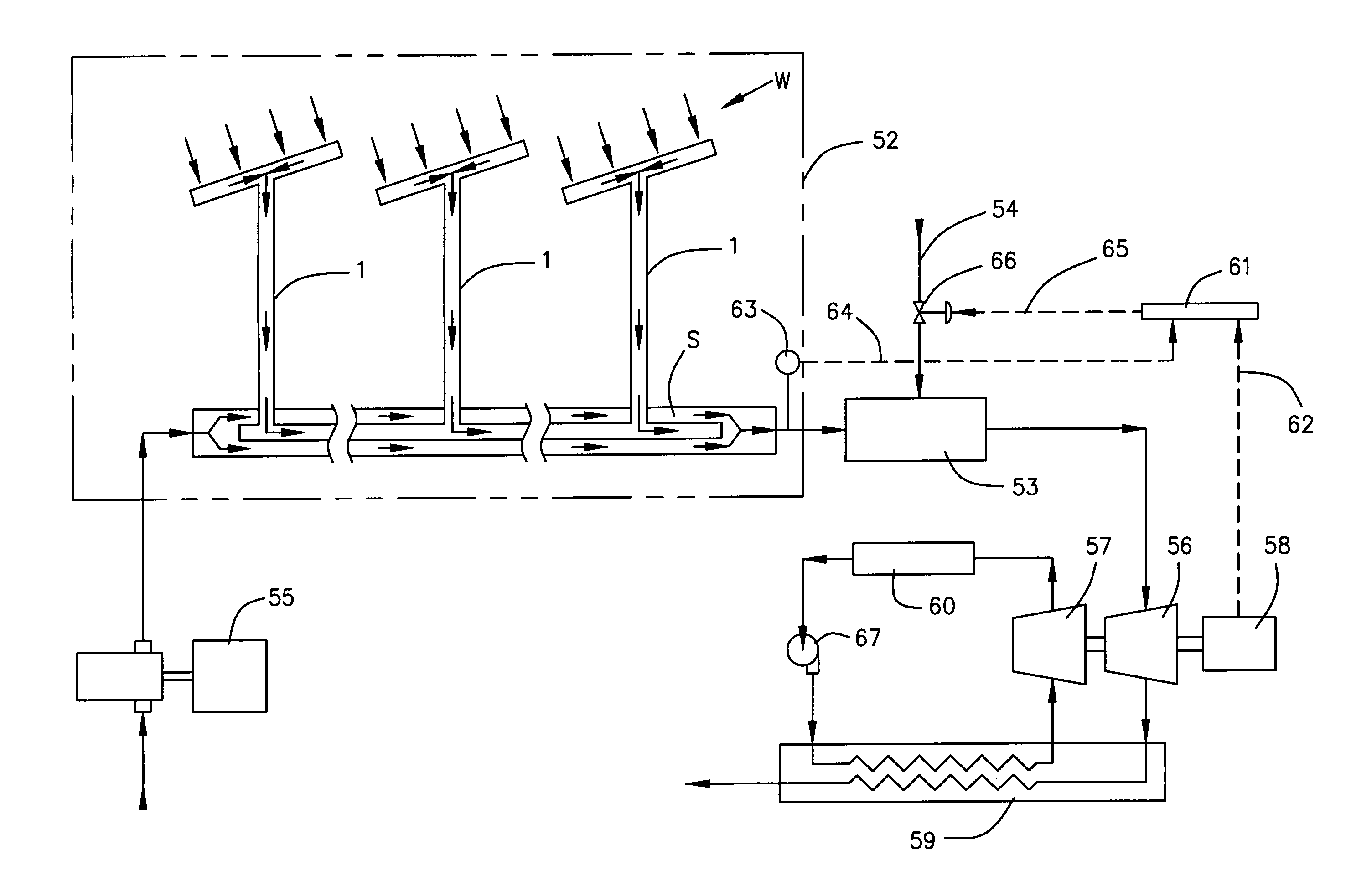
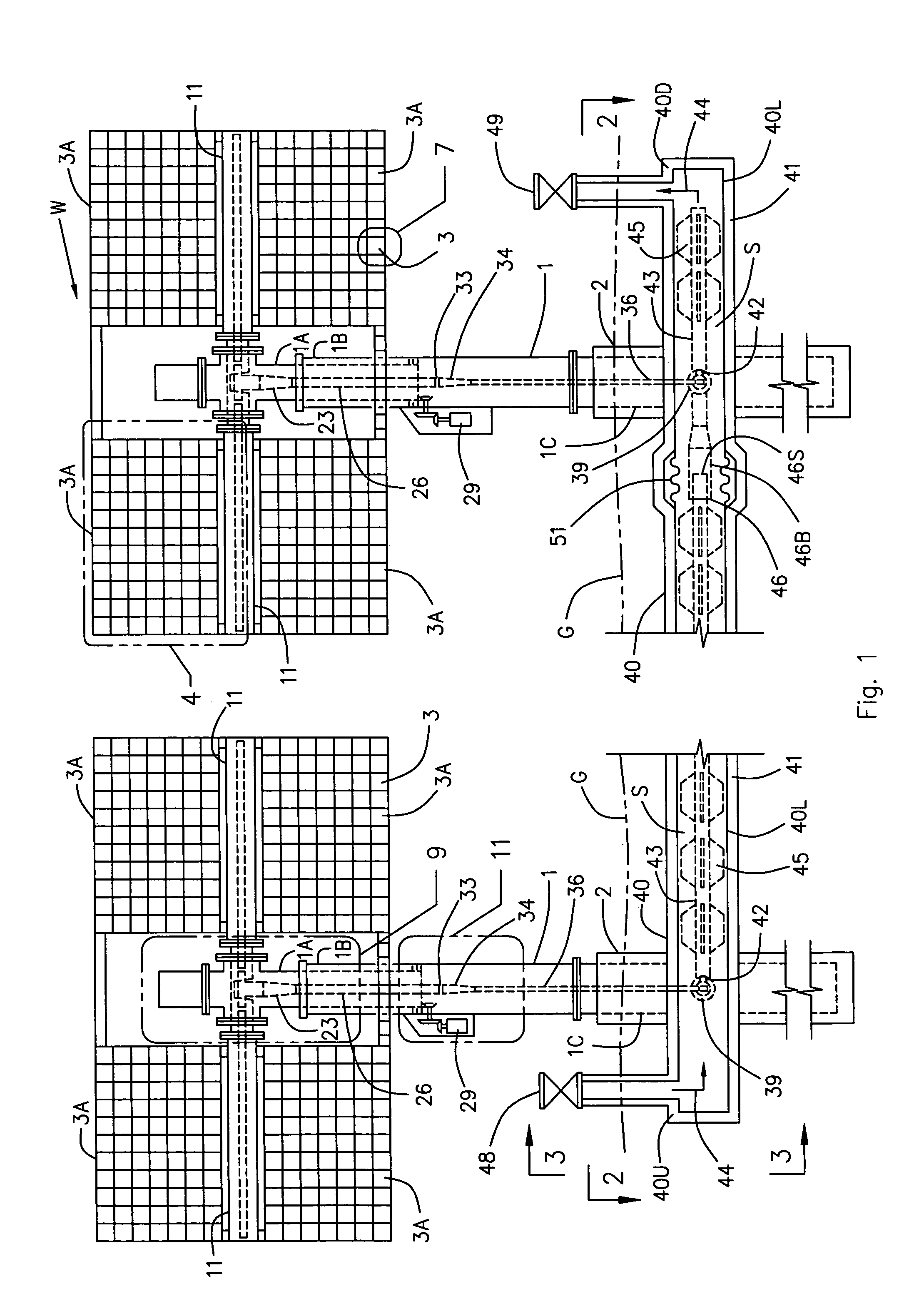
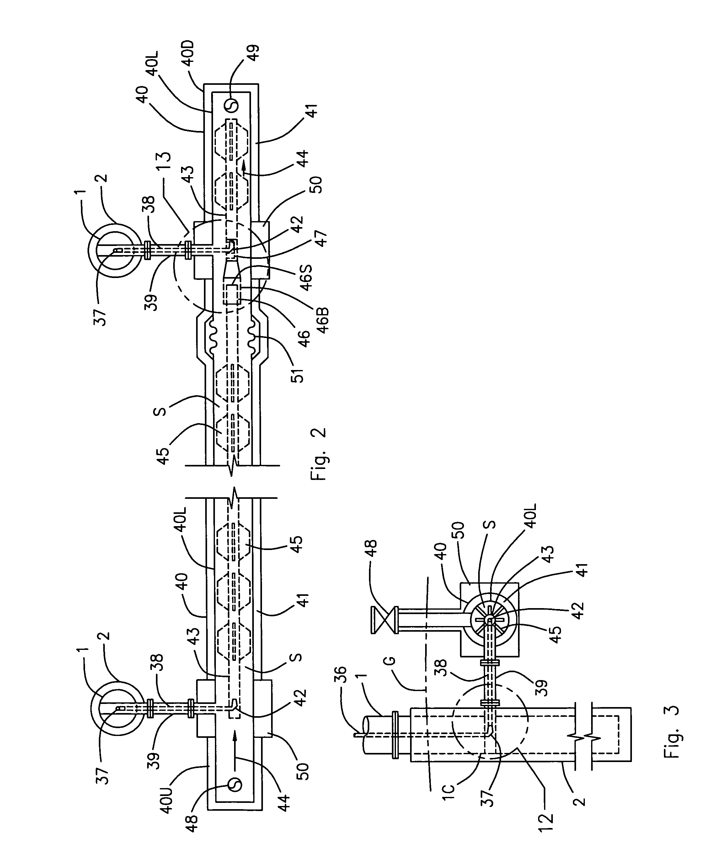
[0039]Referring now to the drawings and initially to FIG. 1, there is illustrated a solar blackbody waveguide W for efficient and effective conversion of solar flux to heat energy that is constructed in accordance with a preferred embodiment of the present invention. As illustrated, the invention W consists of one or more interconnected solar towers 1 to efficiently and effectively capture and concentrate energy in the form of solar flux and to efficiently convert this solar energy into useable forms of heat energy. This embodiment of the invention W is an improvement to simple-cycle and combined-cycle gas turbine heat engines by preheating the air (thermal working fluid) used prior to the combustion chamber of the gas turbine, as will be more fully described hereafter in association with FIG. 17. However, the invention is not limited to this application and is applicable to numerous other heating cycles using different thermal working fluids or heat transfer fluids other than air. ...


PUM


Abstract

A solar blackbody waveguide that captures and uses sunlight to heat a thermal working or heat transfer fluid. Solar cell arrays capture the sunlight. The arrays are movably mounted on solar towers to track the daily movement of the sun and to maintain the proper angle with the horizon throughout the year. The arrays direct the light into a series of light pipes to deliver the light into a solar coil located within an underground insulated pipeline. Energy from the light rays is absorbed by the solar coil and transferred to the thermal working fluid or heat transfer fluid flowing between the solar coil and the insulated pipeline. The energy laden thermal working or heat transfer fluid is removed from the downstream end of the insulated pipeline so that it can be used with existing technologies, such as with a combined cycle gas turbine, boiler, or steam generator.

Description

BACKGROUND OF THE INVENTION[0001]1. Field of the Invention[0002]The present invention relates to a solar blackbody waveguide that captures and uses sunlight to heat a thermal working fluid, such as compressed air. Solar cell arrays are used to capture the sunlight. The arrays are mounted on a plurality of solar towers so that the solar cell arrays can be moved to track the daily movement of the sun and can be tilted to maintain the proper orientation as the angle of the sun with the horizon changes throughout the day and the year. The solar cell arrays direct the light rays into a series of light pipes, optical tees, optical elbows, optical reducers, and solar horns to deliver the light rays into a solar coil located within an underground insulated pipeline that is provided only a few feet away from the base of the solar towers. Energy from the light rays is absorbed by the solar coil and transferred to the pressurized thermal working fluid that flows through an annular space provid...

Claims


Application Information

Patent Timeline
Patent Type & Authority Patents(United States)
IPC IPC(8): F02C1/05F02C1/00F24J2/06F24J2/54F24J2/00F24J2/07F24J2/18F24J2/38F24S20/20F24S23/00F24S23/79F24S50/20
CPCF02C1/05F24J2/067F24J2/07F24J2/18F24J2/542F24J2/38Y02E10/47F24J2/523Y02E10/41F24S20/20F24S23/12F24S23/79F24S25/10F24S30/452F24S50/20H02S20/32H02S40/44Y02E10/50Y02E10/60Y02E10/40
Inventor MECHAM, TRAVIS W.
Owner MECHAM TRAVIS W
Why Eureka
Try Eureka