Light emitting diode lamp with light pipes

a technology of light pipes and diodes, applied in the field of light sources, can solve the problems of increasing installation costs, short life of bulbs, and vibration-induced breakage of thin filaments, so as to reduce costs, reduce costs, and remove heat more effectively

Active Publication Date: 2006-01-31
OSRAM SYLVANIA INC
View PDF3 Cites 87 Cited by
  • Summary
  • Abstract
  • Description
  • Claims
  • Application Information

AI Technical Summary

Benefits of technology

[0009]Elimination of a former metal post that was necessary to carry the heat away from LEDs that were mounted to emit light directly at a reflector from a remote position greatly simplifies construction and reduces cost. Further, mount

Problems solved by technology

While working well and being inexpensive, these bulbs have a relatively short life and, of course, the thin filament employed was always subject to

Method used


Image

  • Light emitting diode lamp with light pipes
  • Light emitting diode lamp with light pipes
  • Light emitting diode lamp with light pipes

Examples


Embodiment Construction

[0014]For a better understanding of the present invention, together with other and further objects, advantages and capabilities thereof, reference is made to the following disclosure and appended claims taken in conjunction with the above-described drawings.

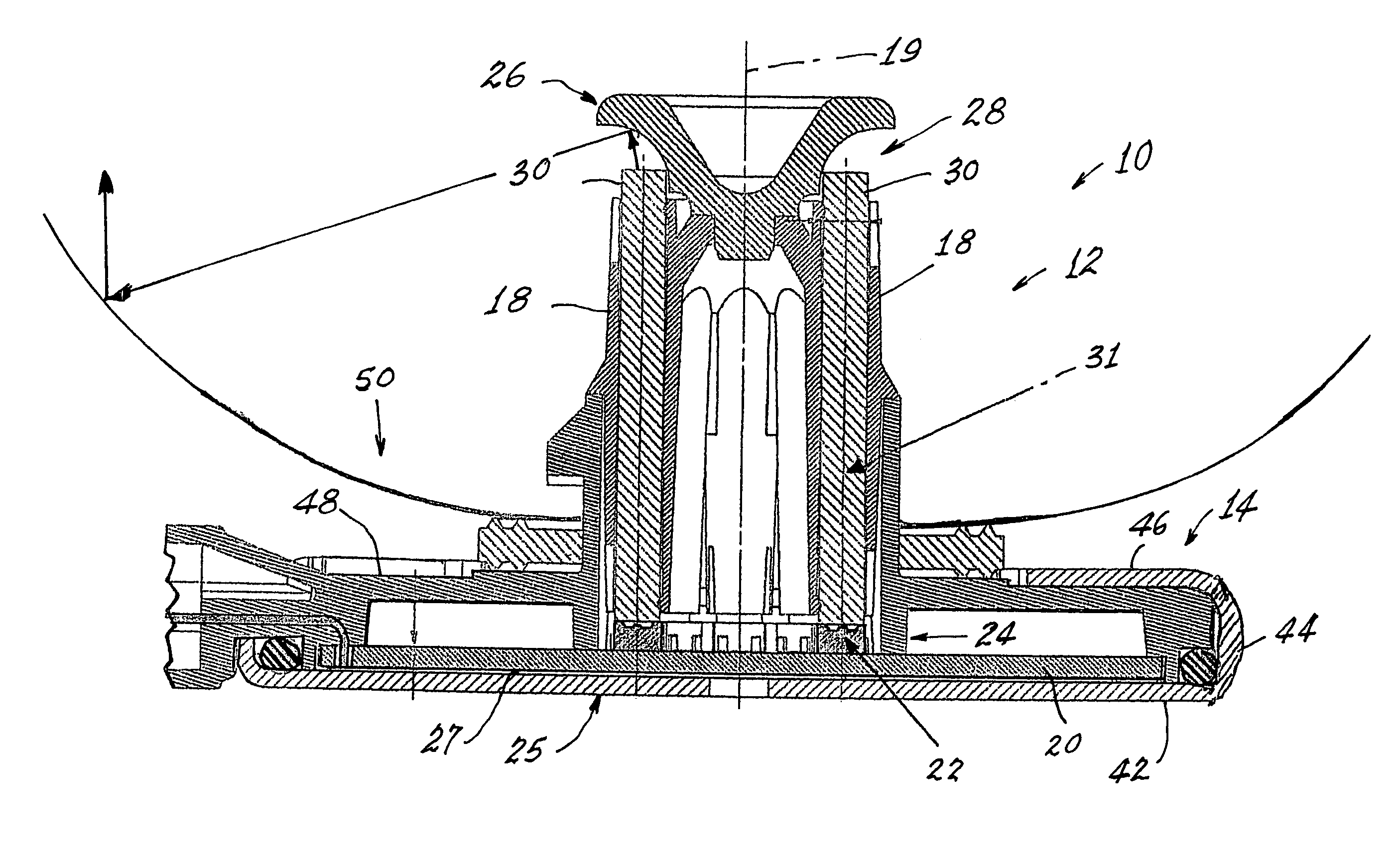
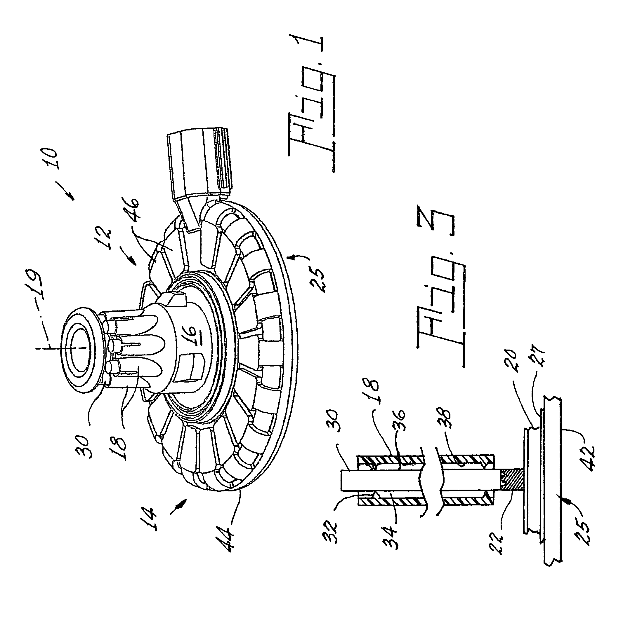
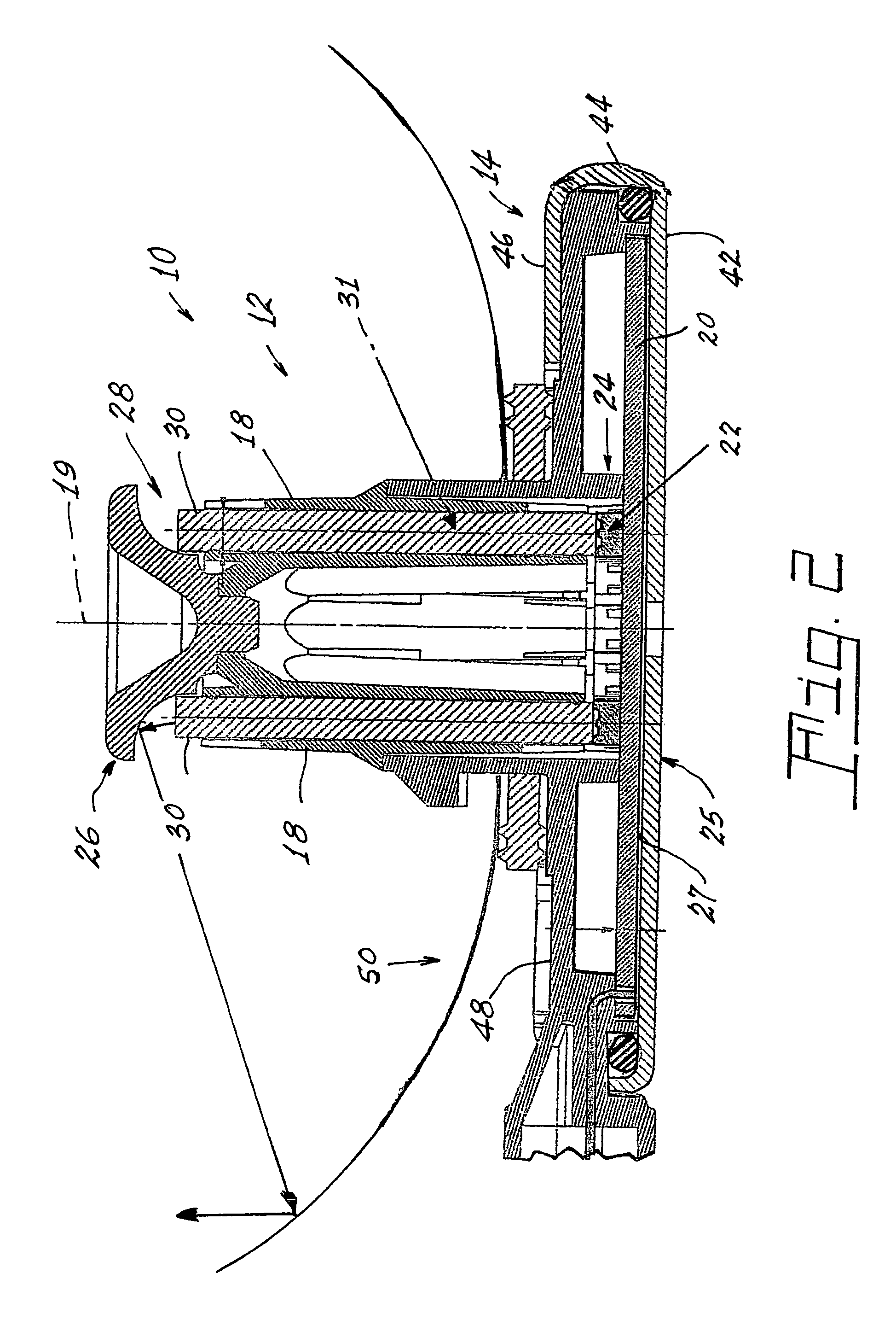
[0015]Referring now to the drawings with greater particularity, there is shown in FIG. 1 an LED light source 10 comprising a housing 12 having a base 14. A hollow core 16 projects from the base 14 and is substantially cylindrical and is surrounded by a plurality of elongated hollow tubes 18. The hollow core 16 and the base 14 are arrayed about a longitudinal axis 19. In a preferred embodiment of the invention there are eight tubes 18; however, the actual number of tubes will be dependent upon the light output of the individual LEDs and, as this light output increases, the number of tubes can be reduced. A printed circuit board 20 (see FIG. 2) is positioned in the base 14 and has a plurality of LEDs 22 operatively fixed thereto. E...


PUM

PropertyMeasurementUnit
Lightaaaaaaaaaa

Abstract

An LED light source has a housing having a base. A core projects from the base; is substantially cylindrical and is surrounded by tubes. The core and the base are arrayed about a longitudinal axis. A circuit board in the base supports LEDs. Each of the LEDs is positioned with one of the tubes in a one-to-one relationship at one end of the core. A heat sink is positioned in a heat-transferring relationship with the circuit board and a first reflector is attached to another end of the core. To direct the light emitted by the LEDs from the source to the reflector, the interior of the tubes can be plated with a highly reflective material. In one embodiment, each of the tubes is fitted with a light guide, each light guide extending from a position immediately above one of the LEDs to a position adjacent the reflector.

Description

CROSS-REFERENCE TO RELATED APPLICATIONS[0001]This application claims priority from Provisional Patent Appln. Ser. No. 60 / 580,287, filed Jun. 16, 2004.TECHNICAL FIELD[0002]This invention relates to light sources and more particularly to light sources employing light emitting diodes (LED or LEDs) and more particularly to light sources useful in the automotive field such as for headlights, taillights, stoplights, fog lights, turn signals, etc. Still more particularly, it relates to such light sources packaged to achieve industry accepted interchangeability.BACKGROUND ART[0003]In the past, most automotive light sources have involved the use of incandescent bulbs. While working well and being inexpensive, these bulbs have a relatively short life and, of course, the thin filament employed was always subject to breakage due to vibration.[0004]Recently some of the uses, particularly the stoplight, have been replaced by LEDs. These solid-state light sources have incredible life times, in the...

Claims


Application Information

Patent Timeline
IPC IPC(8): F21V7/04F21K99/00F21S8/10F21S8/12F21V7/00F21V8/00
CPCF21K9/00F21K9/52F21S48/1159F21S48/1241F21S48/215F21S48/2287F21S48/328F21V29/004F21V29/74F21S48/2293F21V2200/40F21Y2101/02Y10S362/80F21K9/61F21Y2115/10F21S41/143F21S41/24F21S43/14F21S43/247F21S43/251F21V29/767F21S45/48F21S41/151B01D46/0056B01D46/22A61L9/22B01D46/4263B01D46/44B01D46/762
Inventor COUSHAINE, CHARLES M.TUCKER, MICHAELTESSNOW, THOMAS
Owner OSRAM SYLVANIA INC
Why Eureka
Try Eureka