Solid state light source adapted for remote illumination

a light source and solid state technology, applied in the direction of coupling devices, lighting and heating apparatus, radiation therapy, etc., can solve the problems of patient discomfort, patient exposure to excessive heat, and many potentially useful drugs are too toxic to be administered to patients at the desired dose, and achieve high conversion efficiency

Inactive Publication Date: 2007-12-27
AVAGO TECH INT SALES PTE LTD
View PDF5 Cites 84 Cited by
  • Summary
  • Abstract
  • Description
  • Claims
  • Application Information

AI Technical Summary

Problems solved by technology

Many potentially useful drugs are too toxic to be administered to a patient at the desired dose.
In addition, the wavelengths of light needed to provide the conversion of the first drug are outside the range of wavelengths that can be delivered through the skin and intervening tissue.
This arrangement has a number of problems.
First, the patient can be subjected to excessive heat.
Hence, the light bar can become hot enough to cause discomfort to the patient.
Second, there are lower limits on the size of the light bar. The light bar must be large enough to accommodate the LEDs, substrate, and encapsulating material. The number of LEDs can be relatively large, which leads to a device that requires a correspondingly large incision and the medical problems associated with that incision.
Third, there is a limit to the intensity of light that can be provided by such an arrangement. There is a limit to the density of LEDs mounted on a substrate that is set by the size of the LEDs and the amount of heat that must be removed. Since each LED also has a limit on the amount of light generated, the light bar has a maximum light output per unit area. This limit can place restrictions on the types of drugs that can be activated.
Fourth, the light bar must be sterilized. The encapsulation process can provide a reasonable level of sterilization when the device is first made. However, after the bar has been in a patient, it must be re-sterilized, preferably in an autoclave that subjects the light bar to high temperature steam. This process can lead to delaminating the encapsulation layer or stresses on the internal leads. As a result, light bars are typically discarded after use. As a result, the entire device, including the LEDs and wiring must be replaced, which increases the cost of the procedure.

Method used


Image

  • Solid state light source adapted for remote illumination
  • Solid state light source adapted for remote illumination
  • Solid state light source adapted for remote illumination

Examples


Embodiment Construction

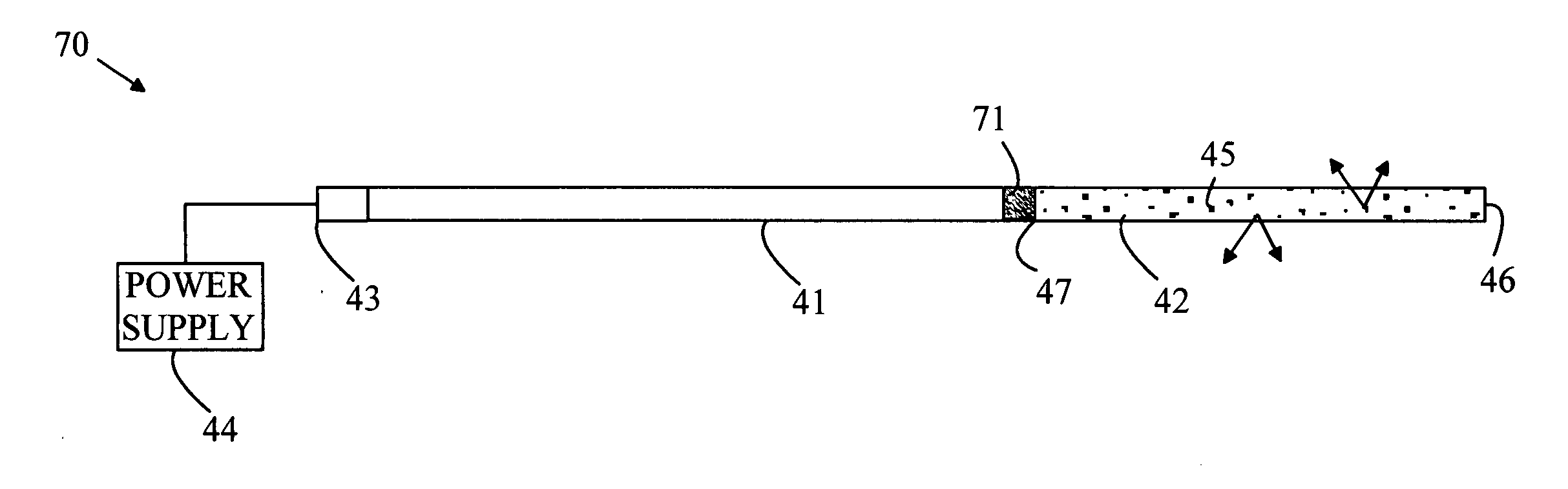
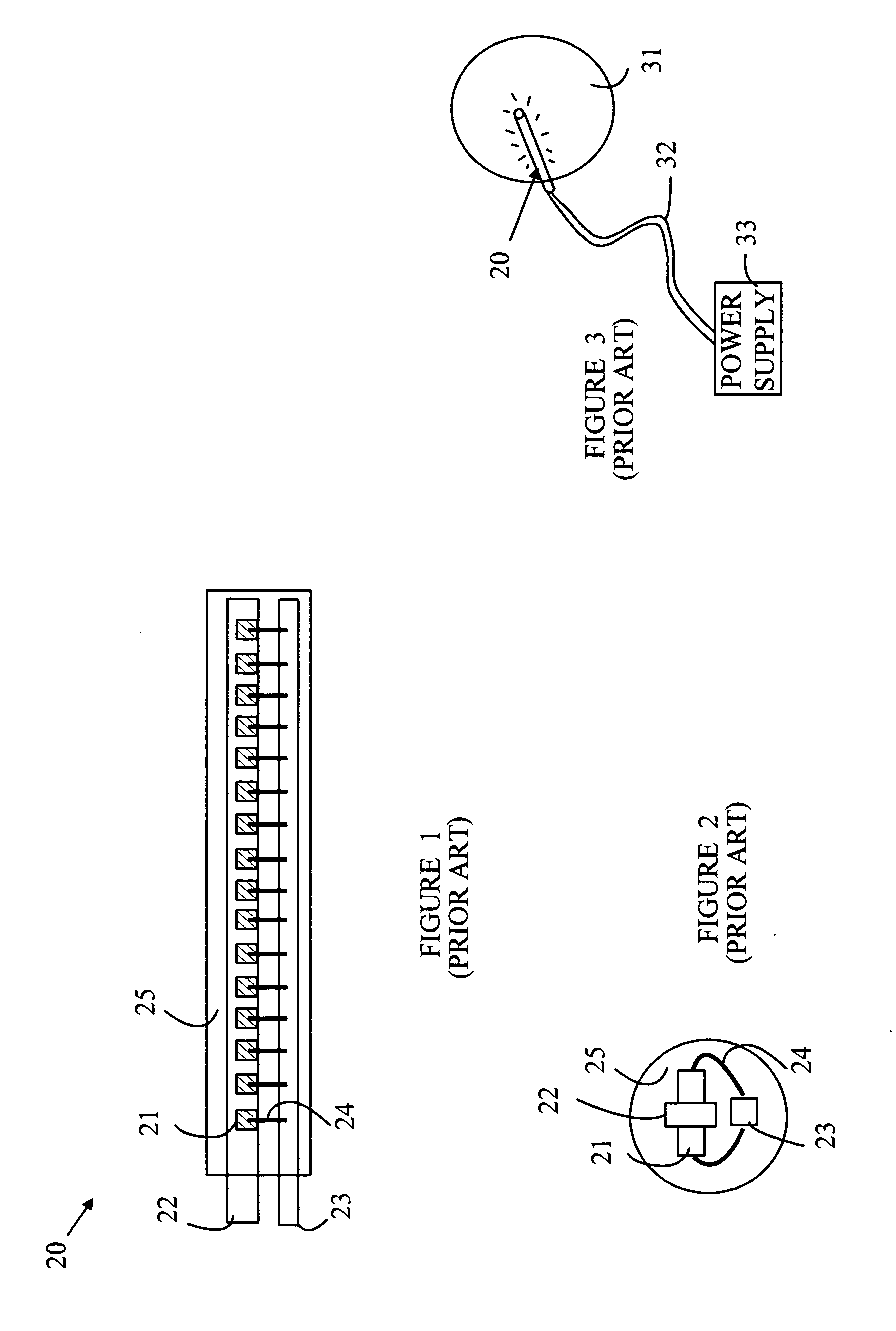
[0020]The manner in which the present invention provides its advantages can be more easily understood with reference to FIGS. 1-3, which illustrate a prior art light bar and the manner in which it is placed in a patient's body during PDT. FIG. 1 is side view of light bar 20, and FIG. 2 is an end view of light bar 20. Light bar 20 is constructed from a plurality of LEDs such as LED 21. Each LED is connected to two conductors 22 and 23. The connections to conductor 22 are made from the bottom of the LED dies, and the connections to conductor 23 are made by wire bonds 24 that connect with a terminal on the top of each LED die. The assembly is encapsulated in a layer of clear medium 25. To provide illumination on both sides of conductor 22, two rows of LEDs are mounted on opposite sides of conductor 22.

[0021]Referring to FIG. 3, light bar 20 is inserted into a body 31 during PDT. Light bar 20 is powered by being connected to an external power supply 33 by a pair of wires 32. Since the w...


PUM


Abstract

A lighting device having a light source, light pipe, and a light-dispensing element is disclosed. The light source emits light at a first wavelength and transmits that light to the light pipe. The light dispensing emitter includes an extended section coupled to the light pipe that emits light along the extended section, the extended section having a side surface through which light exits from the extended section. The extended section can include a medium that is transparent to light of the first wavelength and a plurality of scattering centers, the extended section having a shape such that light that is not scattered by the scattering centers is trapped within the extended section by internal reflection. The extended section can also include a light conversion material that converts light of the first wavelength to light of a second wavelength.

Description

BACKGROUND OF THE INVENTION[0001]Many potentially useful drugs are too toxic to be administered to a patient at the desired dose. One method for achieving the desired advantages while reducing the overall toxicity of the drug to the patient is referred to as photodynamic therapy (PDT). In PDT, a second drug that will enter the site of interest is administered to the patient. The second drug has three properties. First, the second is less toxic than the drug of interest, and hence, is tolerated better by the patient. The second drug can be converted to the first drug at the site of interest by exposing the second drug to light. Third, the amount of the first drug that escapes the site of interest after conversion of the first drug is less than the toxic limit to which the patient can be exposed once the drug is diluted by diffusing through the patient's body.[0002]Most of the treatment sites of interest are internal to the human body. In addition, the wavelengths of light needed to p...

Claims


Application Information

Patent Timeline
Patent Type & Authority Applications(United States)
IPC IPC(8): G02B5/02G02B6/43F21V9/16
CPCA61B2018/2261A61N5/0601A61N5/062G02B6/001A61N2005/0652G02B6/0003A61N2005/063
Inventor NG, KEE YEAN
Owner AVAGO TECH INT SALES PTE LTD
Why Eureka
Try Eureka