Rendering lines with sample weighting

a line weighting and sample technology, applied in static indicating devices, memory adressing/allocation/relocation, instruments, etc., can solve the problems of increasing the complexity of images displayed, increasing the complexity of data being sent to the display device, so as to increase the effect of expanding the width of the displayed line and increasing the anti-aliasing correction factor

Inactive Publication Date: 2005-09-20
ORACLE INT CORP
View PDF13 Cites 72 Cited by
  • Summary
  • Abstract
  • Description
  • Claims
  • Application Information

AI Technical Summary

Benefits of technology

[0031]The rendering unit may evaluate a window function (e.g. by table lookup) for each of said sample positions based on the corresponding sample normal distances. The window function value thereby obtained may be used to determine the sample value (e.g. color value and / or transparency value) at the corresponding sample position. The window function achieves a smooth transition of sample values in the direction normal to the line segment. In one embodiment, the window function achieves a smooth transition of transparency values from totally opaque on the line segment to totally transparency at some normal distance away from the line segment. In another embodiment, the window function achieves a smooth transition of color values from a line color value on the line segment to background color value(s) at some distance away from the line segment.
[0032]The sample-to-pixel calculation units may perform filtering on sample values to generate pixel values. This filtering has an expanding effect on the width of the displayed lines. In some embodiments, the rendering unit may be configured to evaluate the window function on a scalar multiple of the sample normal distances instead of the sample normal distances themselves. In other words, the sample normal distances may be multiplied by an anti-aliasing correction factor to obtain a scaled distance value. The scaled distance value may be used to evaluate the window function. When the anti-aliasing correction factor is greater than one, the line as represented in terms of the sample values is narrower in the normal direction. The narrower line in terms of sample values pre-compensates for the line-expanding effect of the filtering in the sample-to-pixel calculation units. Thus, the line as displayed on screen may appear more consistent with a desired width. As the anti-aliasing correction factor is increased, the apparent width of the line on screen (e.g. on a display screen or a projection screen) is reduced.

Problems solved by technology

Modern graphics systems, however, incorporate graphics processors with a great deal of processing power.
This change is due to the recent increase in both the complexity and amount of data being sent to the display device.
Similarly, the images displayed are now more complex and may involve advanced rendering and visual techniques such as anti-aliasing and texture mapping.
As a result, without considerable processing power in the graphics system, the computer's system CPU would spend a great deal of time performing graphics calculations.
This could rob the computer system of the processing power needed for performing other tasks associated with program execution and thereby dramatically reduce overall system performance.
While this extra performance may be useable in multiple-viewer environments, it may be wasted in the more common single-viewer environments.
For example, an image with a high pixel density may still appear unrealistic if edges within the image are too sharp or jagged (also referred to as “aliased”).
More specifically, anti-aliasing entails removing higher frequency components from an image before they cause disturbing visual artifacts.
While the techniques listed above may dramatically improve the appearance of computer graphics images, they also have certain limitations.
In particular, they may introduce their own aberrations and are typically limited by the density of pixels displayed on the display device.
Prior art graphics systems have generally fallen short of these goals.
These systems, however, have generally suffered from limitations imposed by the conventional frame buffer and by the added latency caused by the render buffer and filtering.
In certain cases, filtering may generate undesirable results, for example, when filtering lines or other objects that have already been anti-aliased.

Method used


Image

  • Rendering lines with sample weighting
  • Rendering lines with sample weighting
  • Rendering lines with sample weighting

Examples


Embodiment Construction

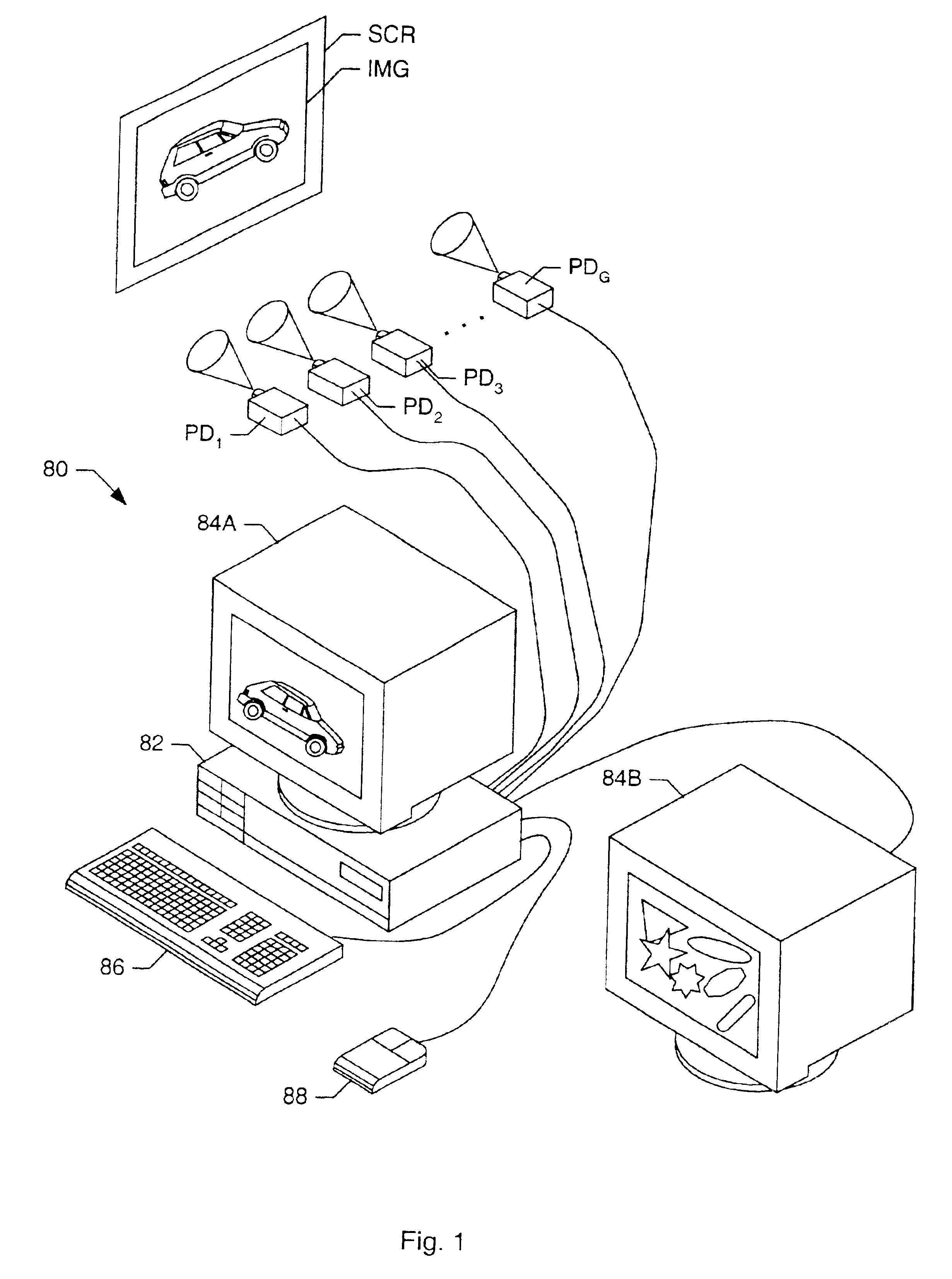
FIG. 1—Computer System

[0066]FIG. 1 illustrates one embodiment of a computer system 80, which performs three-dimensional (3-D) graphics. Computer system 80 comprises a system unit 82 which may couple to one or more display devices such as monitor devices 84A and 84B and / or projection devices PD1 through PDG. Monitor devices 84A and 84B may be based on any of a variety of display technologies. For example, monitor devices 84A and 84B may be CRT displays, LCD displays, gas-plasma displays, digital micro-mirror displays, liquid crystal on silicon (LCOS) display, etc., or any combination thereof. Similarly, projection devices PD1 through PDG may be realized by any of a variety of projection technologies. For example, projection devices PD1 through PDG may be CRT-based projectors, LCD projectors, LightValve projectors, gas-plasma projectors, digital micromirror (DMM) projectors, LCOS projectors, etc., or any combination thereof. Monitor devices 84A and 84B are meant to represent an arbitr...


PUM


Abstract

A graphics system and method for displaying lines on a display device. The system may comprise a sample buffer, a rendering unit and a sample-to-pixel calculation unit. The rendering unit may (a) generate a plurality of sample positions in a two-dimensional space, (b) determine a sample normal distance for each of the sample positions with respect to a line defined by the line-draw command, (c) assign sample values to the sample positions based on the sample normal distance of each of the sample positions, and (d) store the sample values in the sample buffer. The sample-to-pixel calculation unit may read sample values from the sample buffer, filter them to determine a pixel value, and transmit the pixel value to the display device. The rendering unit may render the line sample values with a narrower width to pre-compensate for the line-expanding effect of the filtering performed by the sample-to-pixel calculation unit.

Description

CROSS-REFERENCE TO RELATED APPLICATIONS[0001]This application claims the benefit of U.S. Provisional Application No. 60 / 189,994, filed Mar. 17, 2000, titled “GRAPHICS SYSTEM HAVING A SUPER-SAMPLED SAMPLE BUFFER AND HAVING SINGLE SAMPLE PER PIXEL SUPPORT” by N. David Naegle, Scott R. Nelson, and Michael Deering.[0002]This application claims the benefit of U.S. Provisional Application No. 60 / 175,384, filed on Jan. 11, 2000, titled “Photorealistic Hardware Antialiasing” and U.S. Provisional Application No. 60 / 243,674, filed on Oct. 26, 2000, titled “Renderig Lines With Sample Weighting”.BACKGROUND OF THE INVENTION[0003]1. Field of the Invention[0004]This invention relates generally to the field of computer graphics and, more particularly, to high performance graphics systems.[0005]2. Description of the Related Art[0006]A computer system typically relies upon its graphics system for producing visual output on a computer screen or display device. Early graphics systems were only responsi...

Claims


Application Information

Patent Timeline
Patent Type & Authority Patents(United States)
IPC IPC(8): G06F12/02G06T11/20G09G5/00
CPCG06T11/40
Inventor NELSON, SCOTT R.DEERING, MICHAEL F.RAMANI, NANDINITIAN, MARKSHEHANE, PATRICKTANG, KEVIN
Owner ORACLE INT CORP
Why Eureka
Try Eureka