
Method and apparatus for automatically determining an embedded runout correction threshold

Inactive Publication Date: 2005-09-20
MAXTOR
View PDF10 Cites 10 Cited by
  • Summary
  • Abstract
  • Description
  • Claims
  • Application Information

AI Technical Summary

Problems solved by technology

In an actual system, however, it is difficult to write non-perturbed circular tracks to the data storage disk.
The perturbed shape of these tracks complicates the transducer positioning function during read and write operations because the servo system needs to continuously reposition the transducer during track following to keep up with the constantly changing radius of the track centerline with respect to the center of the spinning disk.
Furthermore, the perturbed shape of these tracks can result in problems such as track squeeze and track misregistration errors during read and write operations.
However, as those skilled in the art will readily appreciate, developing compensation values associated with each and every sector of each and every track is extremely time consuming and, therefore, increases manufacturing times. Furthermore, valuable manufacturing time may be wasted on tracks that have been well-written.
However, if the absolute value of the average PES—RRO for all of the servo sectors in the track are less than the threshold, the track is not corrected.
This may include additional revolutions of position error averaging.
Thus, write position errors will tend to cause encroachment problems and, hence, data destruction.

Method used


Image

  • Method and apparatus for automatically determining an embedded runout correction threshold
  • Method and apparatus for automatically determining an embedded runout correction threshold
  • Method and apparatus for automatically determining an embedded runout correction threshold

Examples


Embodiment Construction

[0028]While this invention is susceptible of embodiments in many different forms, there are shown in the drawings and will herein be described in detail, preferred embodiments of the invention with the understanding that the present disclosure is to be considered as an exemplification of the principles of the invention and is not intended to limit the broad aspects of the invention to the embodiments illustrated.

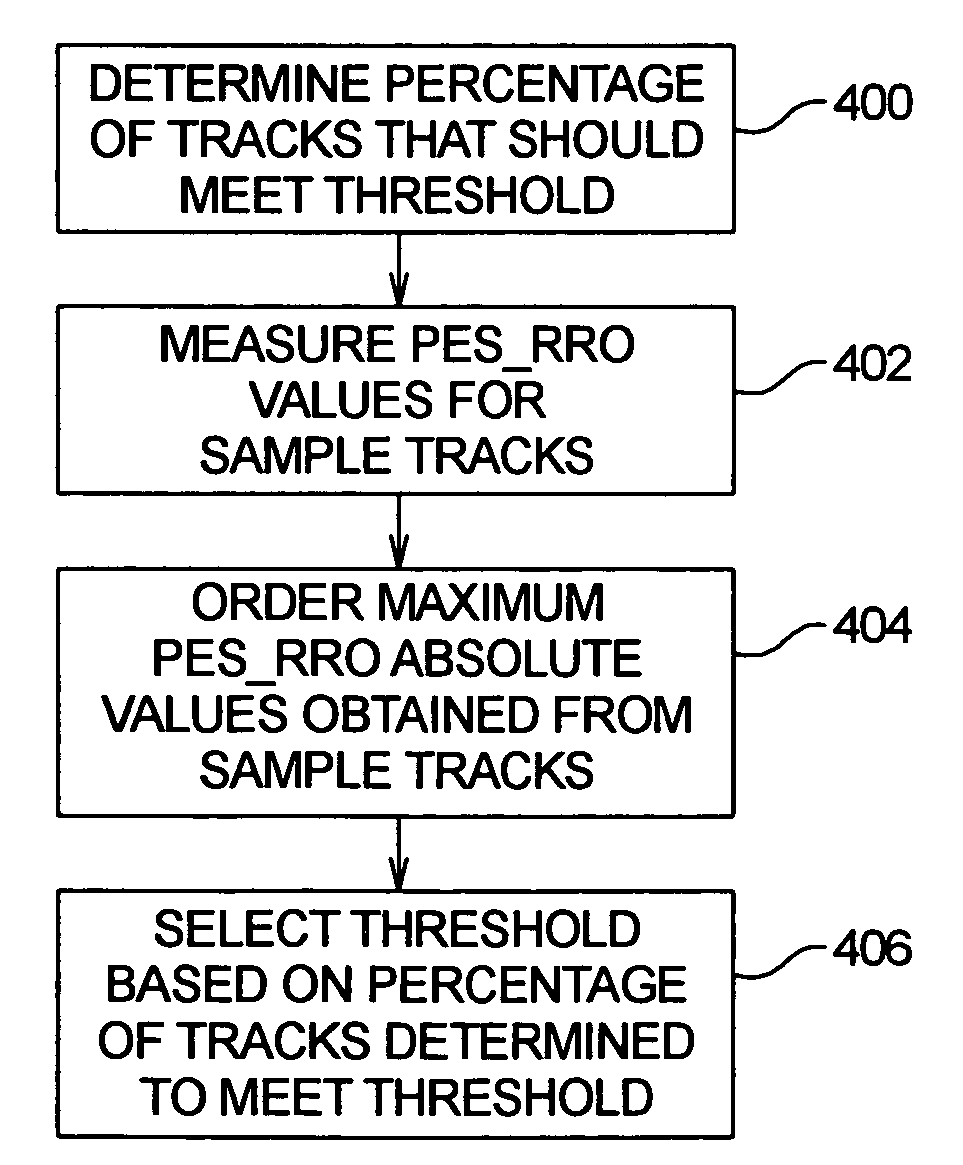
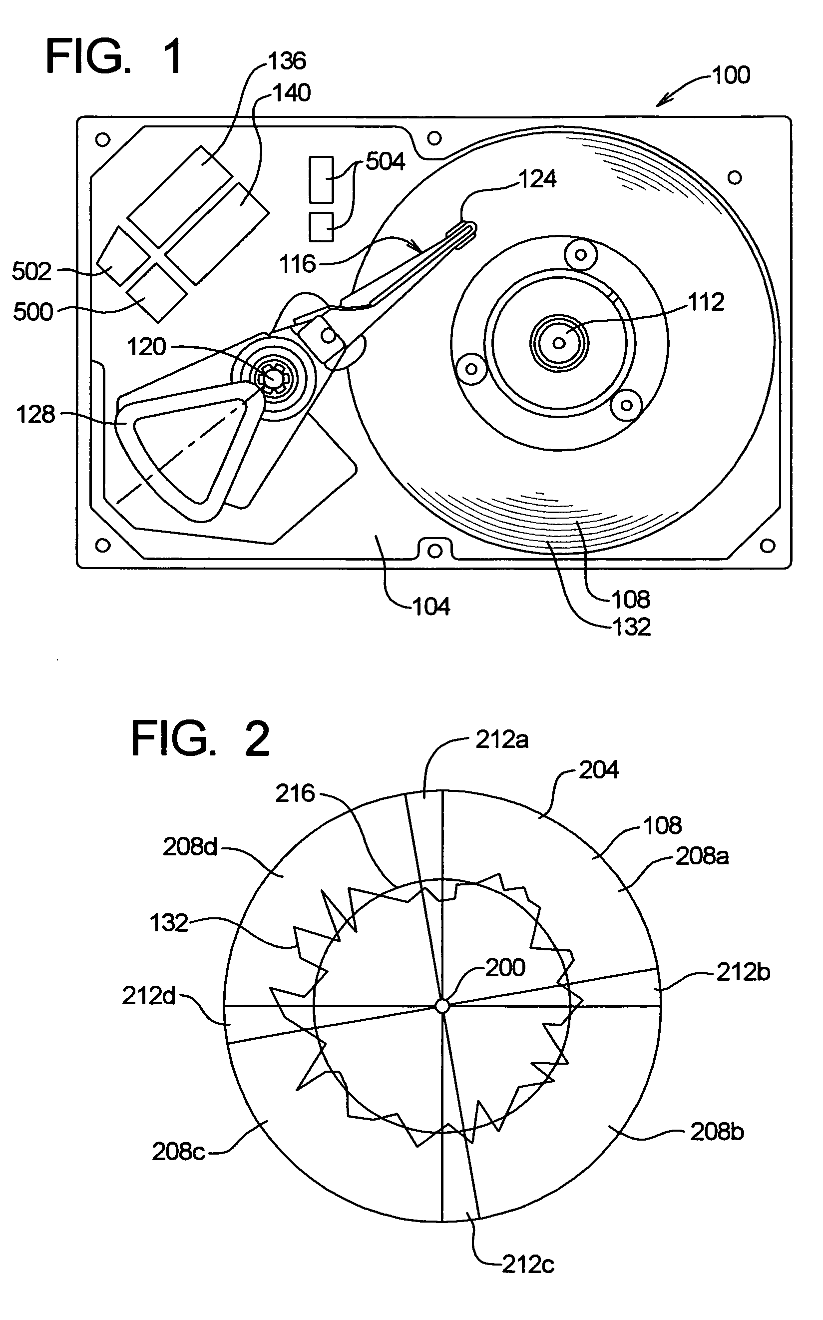
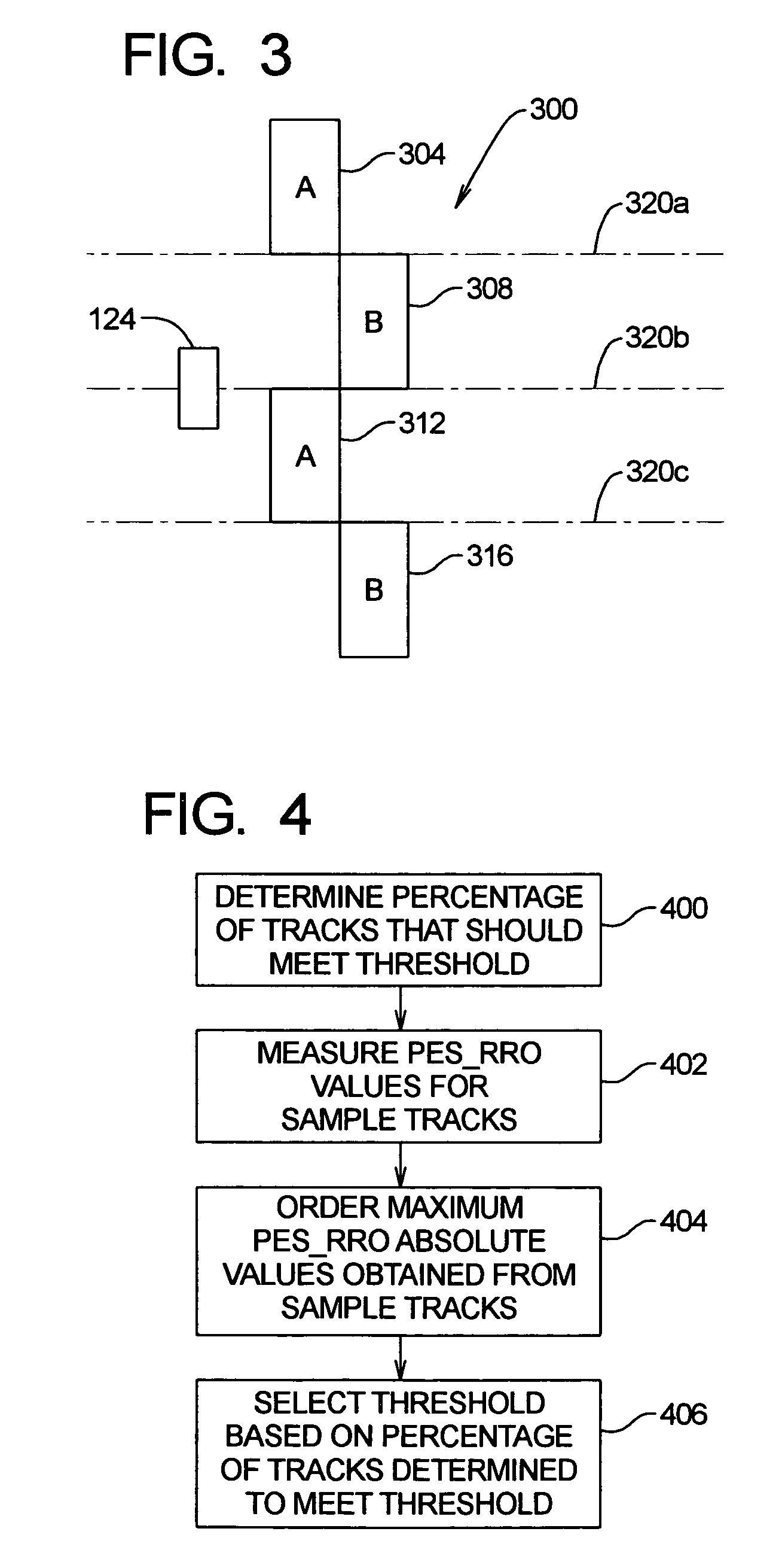
[0029]FIG. 1 is a diagrammatic representation of a computer disk drive with which the present invention may be used. The disk drive, generally identified by reference number 100, includes a base 104 and magnetic disks 108 (only one of which is shown in FIG. 1). The magnetic disks 108 are interconnected to the base 104 by a spindle motor (not shown) mounted within or beneath the hub 112, such that the disks 108 can be rotated relative to the base 104. Actuator arm assemblies 116 (only one of which is shown in FIG. 1) are interconnected to the base 104 by a bearing 120. The ac...


PUM


Abstract

A method and apparatus for automatically determining an embedded runout correction threshold for a disk drive are disclosed. In prior systems, embedded runout correction thresholds were set for all disk drives in a production run. The present invention provides a technique for automatically determining an embedded runout correction threshold on a drive-by-drive basis, instead of a production run of drives basis.

Description

CROSS-REFERENCE TO RELATED APPLICATION[0001]Priority is claimed from U.S. Provisional Patent Application Ser. No. 60 / 257,135 filed Dec. 20, 2000, which is incorporated by reference herein in its entirety.FIELD OF THE INVENTION[0002]The present invention relates to transducer positioning in a magnetic data storage system, such as a computer disk drive. More particularly, the present invention relates to a method and apparatus for automatically determining an embedded runout correction (ERC) threshold, which may be used within a system to compensate for repetitive run-out (RRO) created during servo track write in a magnetic data storage system.BACKGROUND OF THE INVENTION[0003]A disk drive is a data storage device that stores digital data in tracks on the surface of a data storage disk. Data is read from or written to a track of the disk using a transducer, which includes a read element and a write element, that is held close to the track while the disk spins about its center at a subs...

Claims


Application Information

Patent Timeline
IPC IPC(8): G11B5/596
CPCG11B5/59627
Inventor HARGARTEN, JIMMELROSE, THOMASPURKETT, JOHN
Owner MAXTOR
Learn More