

Methods and apparatus for characterizing board test coverage
a characterizing board and test coverage technology, applied in the field of characterizing board test coverage, can solve the problems of erroneous assumption that a device with working tests is a sufficiently tested device, meaningless application of the “old” board test coverage model, and limited in the number of defects they can tes
- Summary
- Abstract
- Description
- Claims
- Application Information
AI Technical Summary
Problems solved by technology
Method used
Image

Examples
first embodiment
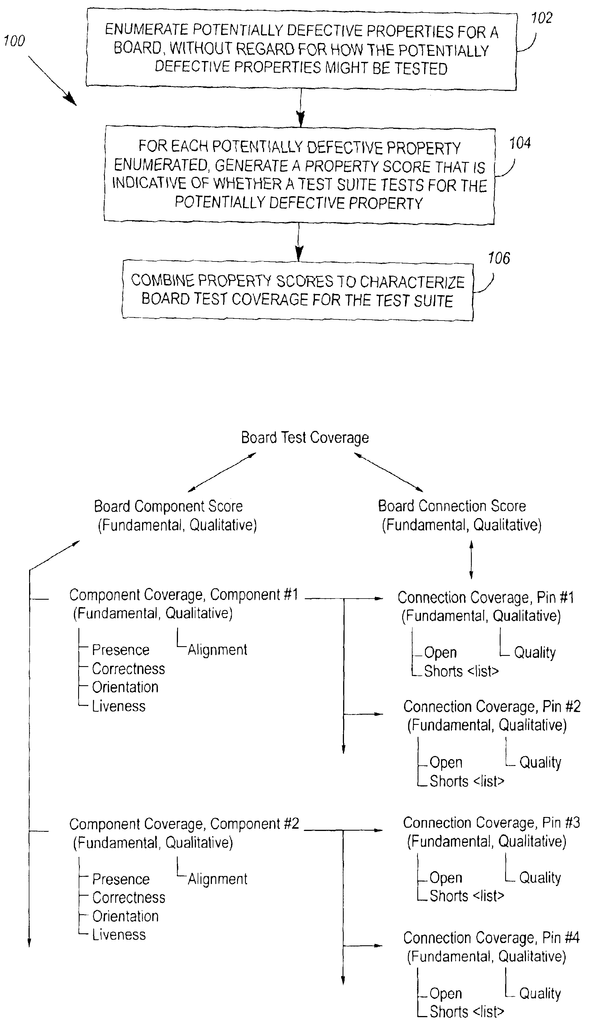
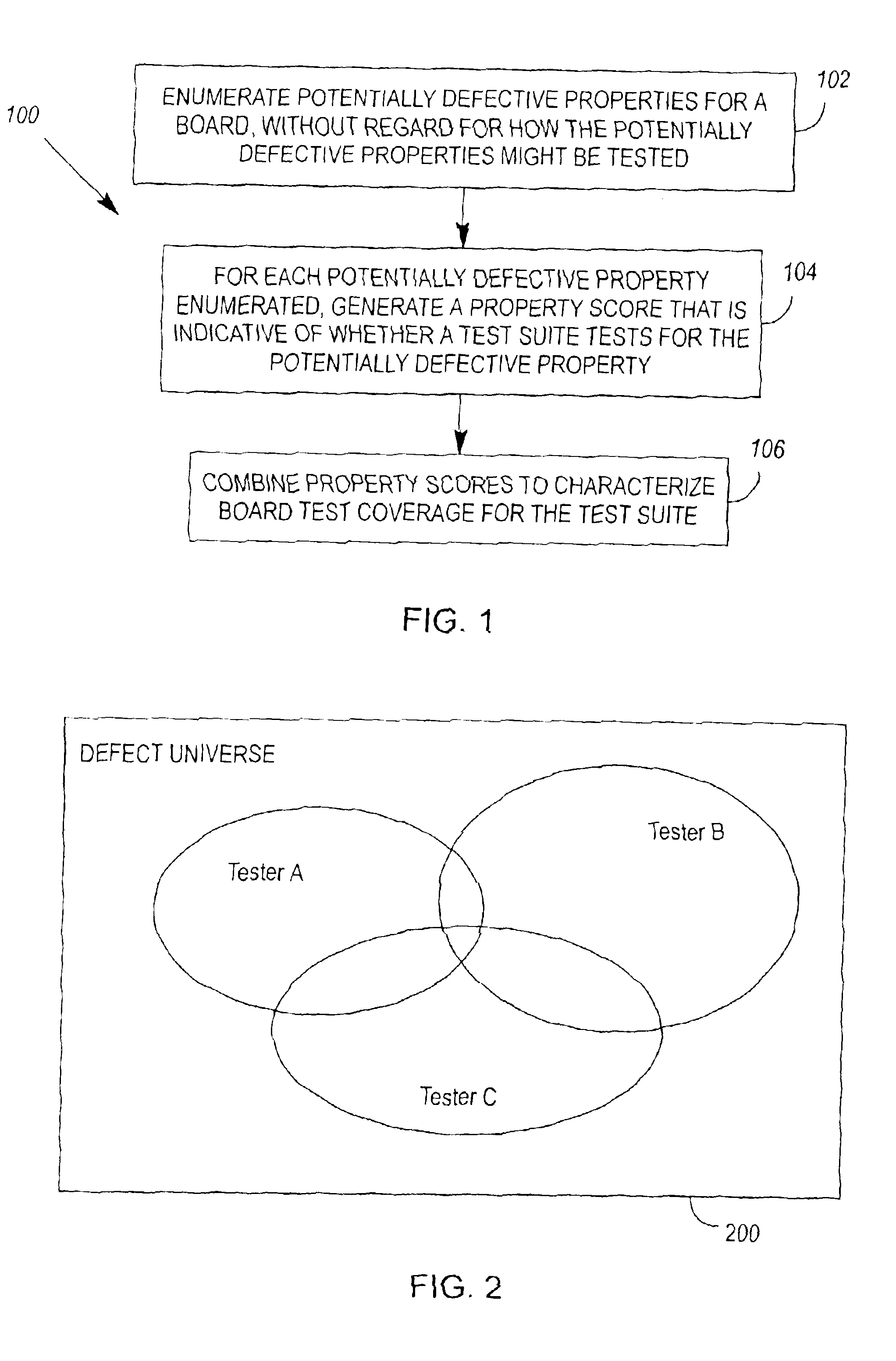
[0189]FIG. 9 illustrates apparatus 900 for characterizing board test coverage. The apparatus 900 comprises 1) means 902 for enumerating potentially defective properties for a board, without regard for how the potentially defective properties might be tested, 2) means 904 for determining and scoring, in relation to each potentially defective property enumerated, whether a test suite tests for the potentially defective property, and 3) means 906 for combining scores to characterize board test coverage for the test suite. By way of example, the apparatus 900 could take the form of software, firmware, hardware, or some combination thereof. In one embodiment of the apparatus, each of its components is embodied in computer readable program code stored on computer readable storage media such as: a CD-ROM, a DVD, a floppy disk, a hard drive, or a memory chip.
second embodiment
[0190]FIG. 10 illustrates apparatus for characterizing board test coverage. The apparatus is embodied in computer readable program code 1006, 1012, 1016, 1018 stored on computer readable storage media 1000. A first portion of the program code 1006 builds a list 1008 of potentially defective properties for a board. The code does this by parsing descriptive information 1002 for the board to extract component and connection information for the board, and then associating potentially defective properties 1004 with the extracted component and connection information. A second portion of the program code 1012 parses a test suite 1010 and extracts test objects 1014 therefrom. Each test object 1014 comprises the details of a test, and a list of components and connections that are tested by the test. A third portion of the program code 1016 associates the test objects 1014 with entries in the list 1008 of potentially defective properties, by identifying common components and connections in ea...
third embodiment
[0197]FIG. 11 illustrates apparatus for characterizing board test coverage. Again, the apparatus is embodied in computer readable program code 1102 stored on computer readable storage media 1100. Unlike the apparatus illustrated in FIG. 10, the apparatus illustrated in FIG. 11 does not participate in building a list of a board's potentially defective properties. Rather, program code 1102 parses an existing test suite and list of potentially defective properties for a board, and then assigns property scores to potentially defective properties in response to whether the test suite tests for the potentially defective properties.
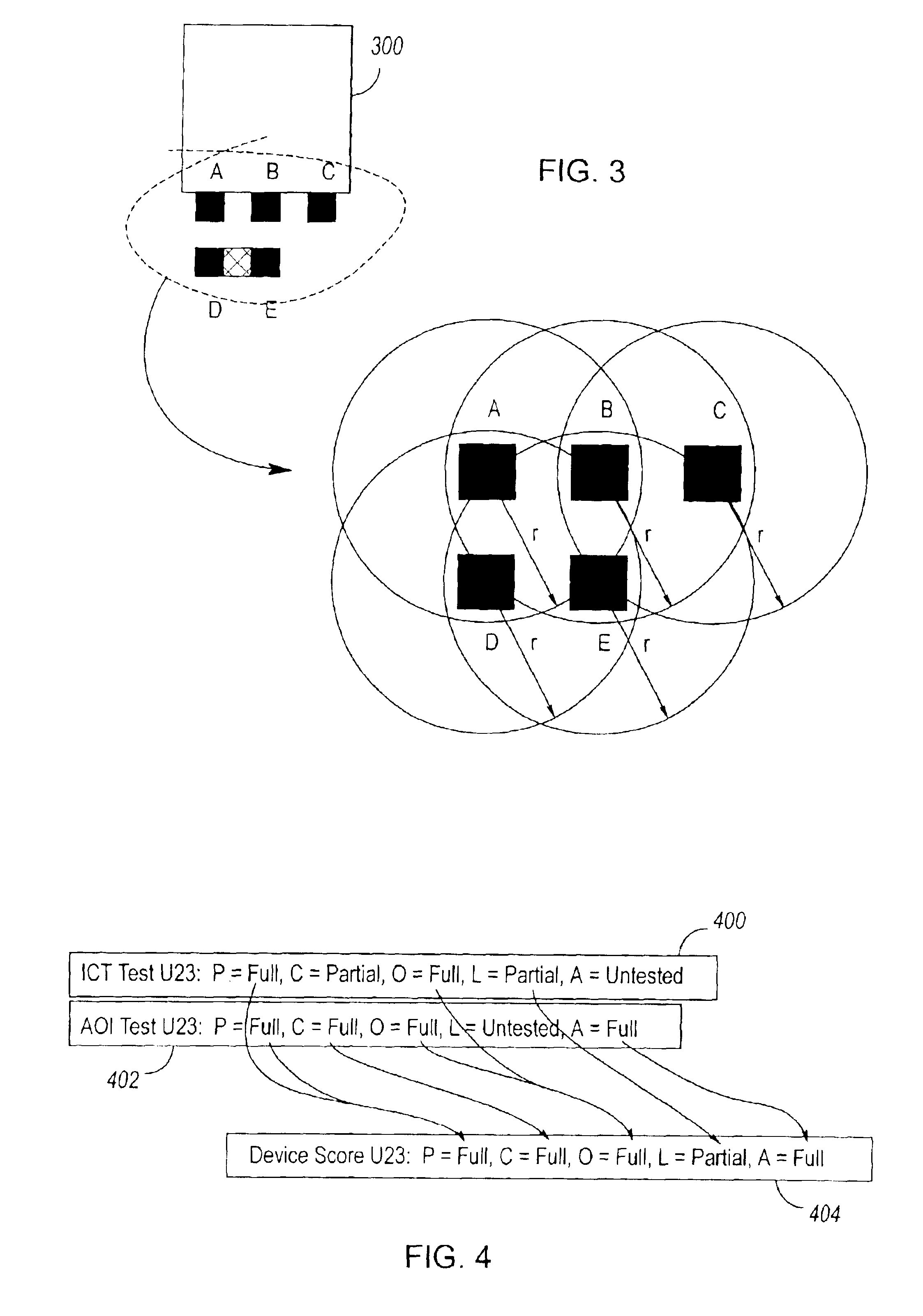
[0198]In one embodiment of the FIG. 11 apparatus, property scores comprise numerical equivalents for: Fully Tested, Partially Tested, and Untested.
[0199]When a potentially defective property is tested by two or more tests in a test suite, and two or more property scores exist for the same potentially defective property, additional program code can combine two or...
PUM
 Abstract
Description
Claims
Application Information