Plumb-bob

a technology of plumb-bob and bob-bob, which is applied in the field of improved plumb-bob, can solve the problems of easy loss, inconvenient use, and difficult to properly keep the replacement point i from being damaged by careless contact, and achieve excellent fixing and holding

Inactive Publication Date: 2005-09-27
CLEAR DAWN
View PDF12 Cites 4 Cited by
  • Summary
  • Abstract
  • Description
  • Claims
  • Application Information

AI Technical Summary

Benefits of technology

[0009]Yet, another object of the invention is to provide an improved plumb-bob, further comprising a spring-ring arranged between the point section and the fixing element. By means of the constraint force provided by the spring-ring, not only it is possible to provide the point section with an excellent fixing and holding effect, but also the resilience provided by the same may indeed prevent the assembly from loosing.
[0010]Following drawings are cooperated to describe the detailed structure and its connective relationship according to the invention for facilitating your esteemed members of reviewing committee in understanding the characteristics and the objectives of the invention.

Problems solved by technology

However, any careless contact between the point and the ground or other hard surface during the operation will dull or skew the point such that the vertical level can not be marked correctly and thus the plumb-bob with dulled and skewed point should be replaced by a new one.
However, the package of FIG. 2B is not only inconvenient for the user to carry the replacement point I and easy to lose it, but also it is a tough job to properly keep the replacement point I from damaging by any careless contacting.
In addition, The point section E with threaded potion H is costly to make and is difficult to find a substitute for the same after the original point E is damaged, since the diameter and thread pitch of the threaded portion H of the point section E has to match with those of the threaded portion of the chamber G. The shortcoming of uneasy to purchase the substitute is also true for the plumb-bob disclosed in the U.S. Pat. No. 3,448,525.
When the point J and the spring-ring L are damaged and are required to be changed, the user will face the same problem as described above.

Method used


Image

  • Plumb-bob
  • Plumb-bob
  • Plumb-bob

Examples


Embodiment Construction

[0018]Please refer to FIG. 4 and FIG. 5, which are the 3-D explosive view and the cross-sectional view of an assembled plumb-bob of the present invention. The improved plumb-bob disclosed by the invention is mainly consisted of a body section 1, a point section 2, and a fixing element 3, wherein a connecting means 11 is arranged at the top of the body section 1 by which it may be connected to a suspending cord 4, and the point section 2 is a cylinder with a flange 21 arranged at the shank thereof, and the point section 2 is provided at least at one end with a conical-pointed part 22, and the fixing element is bored from the low end to the upper end forming an upper portion 31 and a lower portion 32. The upper portion 31 is of larger diameter and the lower portion 32 is of reduced diameter but is larger than that of the point section 2, thus forming an angular shoulder against which the fringe 21 abuts when the parts are assembled to enable the conical-pointed part 21 to project outw...


PUM


Abstract

The improved plumb-bob is mainly consisted of a body section, a point section, and a fixing element, wherein a connecting means is arranged at the top of the body section by which it may be connected to a suspending cord, and the point section is a cylinder with a flange arranged at the shank, and the point section is provided at least at one end with a conical-pointed part, and the fixing element is bored from the low end to the upper end forming an upper portion and a lower portion. The upper portion is of larger diameter and the lower portion is of reduced diameter but is larger than that of the point section, thus forming an angular shoulder against which the fringe abuts when the parts are assembled to enable the conical-pointed part to project outwardly under the fixing element. The fixing element can hold and fix the point section in a proper position between the body and the fixing element. The invention may simplify the structure of the expandable point section such that not only the manufacturing cost of the point section is reduced, but also many unnecessary compatible constraints may be removed, that is, when the point section is damaged and no spared point section for replacement, a metal nail, such as iron nail, steel nail, etc., with similar diameter can be applied as a substitute.

Description

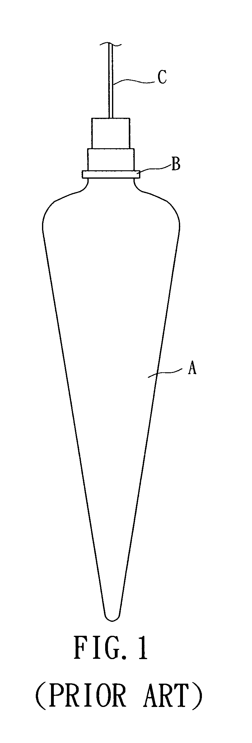
[0001]1. Field of the Invention[0002]The invention relates to an improved plumb-bob, and more particularly, to an improved plumb-bob having advantages as following: easy to carry and safekeeping, easy to get the replacement for the expandable point, and low cost.[0003]2. Background of the Invention[0004]Generally, when a construction is underway, no matter bricklayers or other artisans must use certain auxiliary tools to help measuring or marking a level. Plumb-bob is the most commonly used tool for the jobs. The outer appearance of a conventional Plumb-bob A, as shown in FIG. 1, is a cone shape, and at the top thereof has means B by which it may be connected to a suspending cord C. By holding the suspending cord C, the plumb-bob A can be dropped and hanged due to gravity. When the plumb-bob A is still, a level can be marked by the tapered point of the plumb-bob. However, any careless contact between the point and the ground or other hard surface during the operation will dull or sk...

Claims


Application Information

Patent Timeline
Patent Type & Authority Patents(United States)
IPC IPC(8): G01C15/10
CPCG01C15/10
Inventor LIN, MING-CHENG
Owner CLEAR DAWN
Why Eureka
Try Eureka