Excess tire air pressure relief valve

a tire and air pressure technology, applied in the field of excess tire air pressure relief valves, can solve the problems of “blowout”, most vehicle owners are not accustomed to examining tires, and are not aware of proper pressure levels, so as to prevent air leakage through the tube and relieve the pressure within the tir

Inactive Publication Date: 2005-09-27
WILLIAMS HAROLD
View PDF13 Cites 20 Cited by
  • Summary
  • Abstract
  • Description
  • Claims
  • Application Information

AI Technical Summary

Benefits of technology

[0011]To attain this, the present invention essentially comprises an excess tire air pressure relief valve positioned on an automobile tire for relieving the pressure within the tire caused by heat or over inflation. The valve has a main tube that extends through the tire rim, to selectively communicate air from the tire interior to the tire exterior. The tube has a spring that extends between a pair of disks. A seal is positioned below the spring support disk and is pressed against a lower lip by the spring to prevent air leakage through the tube. The disks do not tightly fit against the main tube inner wall, thereby allowing air to escape around the disk edges when the seal is raised. The spring is selected to exert sufficient force against the seal to prevent air leakage through the main tube. When internal pressure is greater than normal within the tire, the spring is urged outward, allowing air to escape around the edges of the spring support disk until the internal pressure lowers such that the spring can once again hold the seal tightly against the bottom lip.
[0012]It is an object of the invention to produce an excess tire air pressure relief valve that prevents a tire from remaining overinflated. Accordingly, the valve automatically dispels air that exceeds the recommended pounds of pressure per square inch (psi) for the tire.

Problems solved by technology

Low pressure can cause a flat tire and too much pressure, or over inflation, can result in a “blow out” while driving.
Most vehicle owners are unaware of the proper pressure levels for their tires and are not accustomed to examining the tires on a regular basis.
Inadequate tire pressure can cause damage to the tire which may result in a dangerous condition on the road.
Accordingly, the over inflation ‘problem’, becomes more severe once the car is driven, when the danger of a blow out can have serious consequences.

Method used


Image

  • Excess tire air pressure relief valve
  • Excess tire air pressure relief valve
  • Excess tire air pressure relief valve

Examples


Embodiment Construction

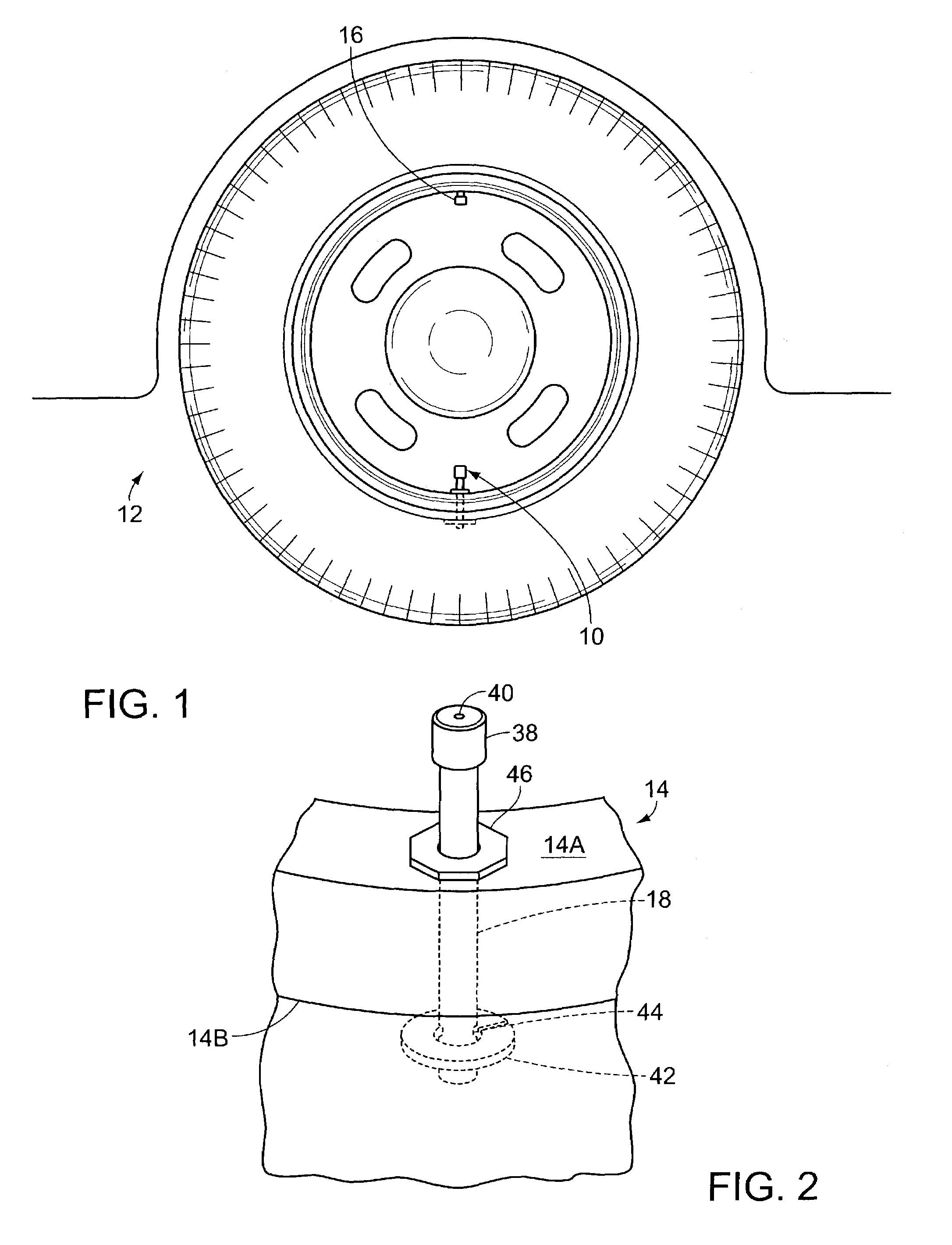
[0046]FIG. 1 illustrates an excess tire air pressure relief valve 10 positioned on an automobile tire 12. A standard tire 12 has an outer rim 14 that extends around the tire 12, wherein an interior volume is contained within the confines of the rim 14. The rim 14 has an outer surface 14A and an inner surface 14B. The tire 12 further comprises an inflation valve 16 through which air is pumped into the interior volume of the tire 12. The excess tire air pressure relief valve 10 extends from exterior to the tire 12, through the tire outer rim 14, and into the tire interior volume. The relief valve 10 dispenses excess air from within the tire 12 to reduce the pressure within said tire 12.

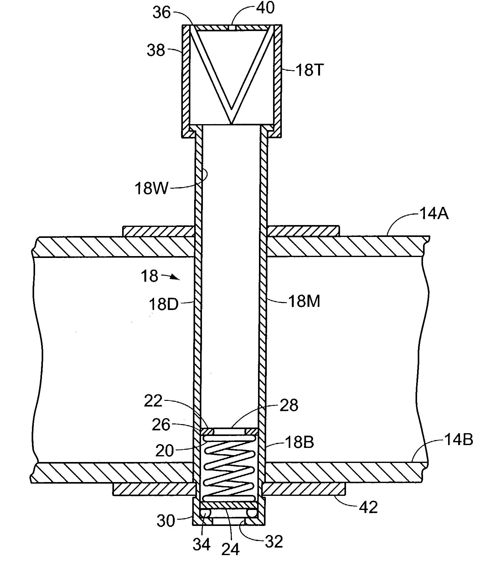
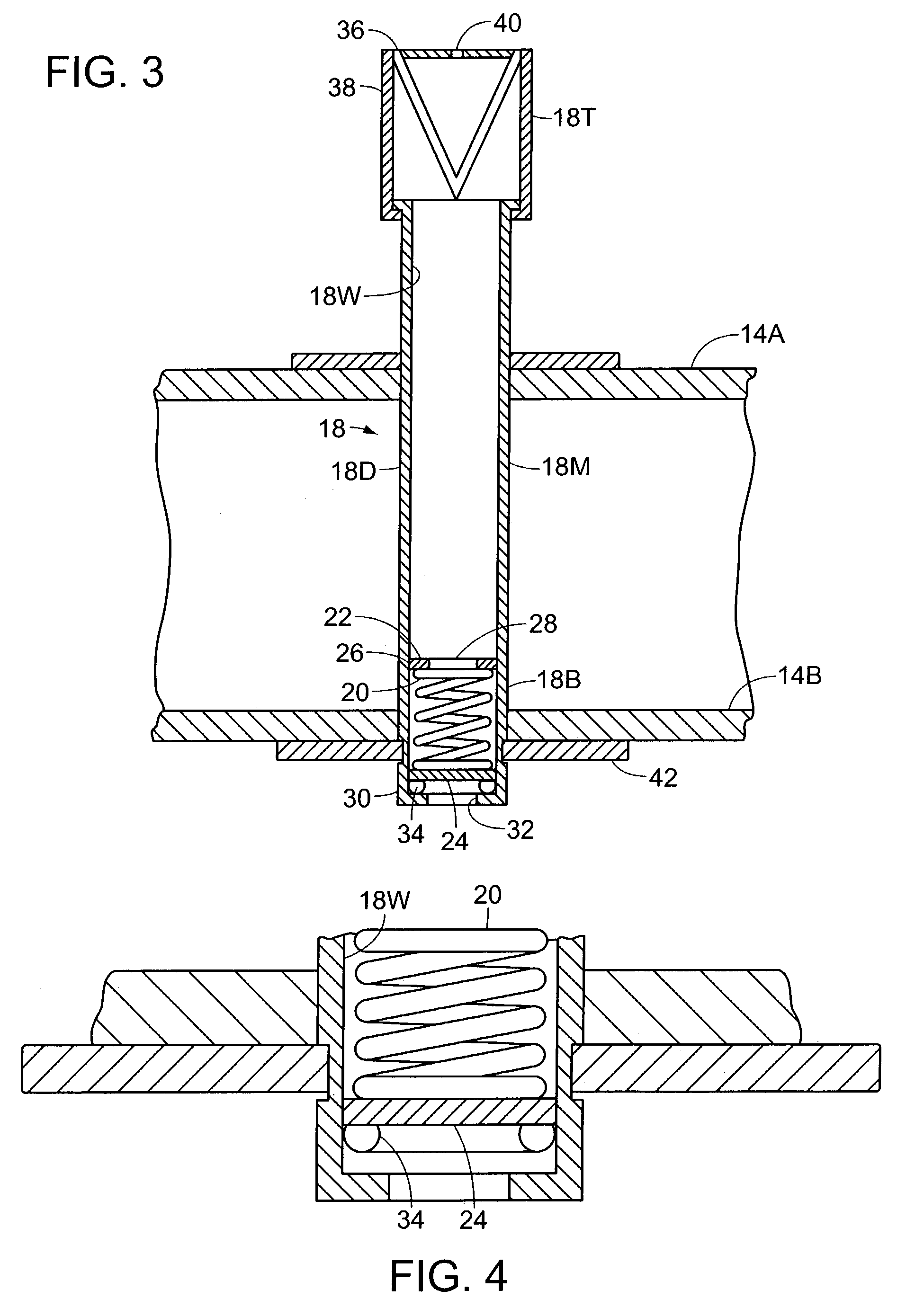
[0047]The relief valve 10 comprises a main tube 18 that extends through the tire rim 14, from the rim outer surface 14A to the rim inner surface 14B, and an air release assembly housed within the main tube. The main tube 18 has an outer wall 18D, an inner wall 18W, a top portion 18T that extends above t...


PUM


Abstract

An excess tire air pressure relief valve positioned on an automobile tire for relieving the pressure within the tire caused by heat or over inflation. The valve has a main tube that extends through the tire rim, to selectively communicate air from the tire interior to the tire exterior. The tube has a spring that extends between a pair of disks. A seal is positioned below the spring support disk and is pressed against a lower lip by the spring to prevent air leakage through the tube. The spring is selected to exert sufficient force against the seal to prevent air leakage through the main tube. When internal pressure is greater than normal within the tire, the spring is urged outward, allowing air to escape around the edges of the spring support disk until the internal pressure lowers such that the spring can once again hold the seal tightly against the bottom lip.

Description

BACKGROUND OF THE INVENTION[0001]The invention relates to an excess tire air pressure relief valve. In particular, the invention is a valve installed within the tire, wherein upon exceeding a pre-determined level of pressure, the valve automatically releases the air from the tire and thereby decreases the pressure to a safe level.[0002]Automobiles have become increasingly popular, with most households owning and / or using at least one car. The owner of an automobile has the responsibility of caring for and maintaining the automobile to ensure that the vehicle does not break down. Such maintenance includes periodic oil changes, fluid transfers, and tire rotations.[0003]Most vehicles have four tubeless radial tires. It is necessary that the tires be durable and resistant to wear and tear. Further, it is necessary that the vehicle owner routinely check the air pressure in the tires. Low pressure can cause a flat tire and too much pressure, or over inflation, can result in a “blow out” w...

Claims


Application Information

Patent Timeline
Patent Type & Authority Patents(United States)
IPC IPC(8): F16K15/20F16K15/00B60C29/06F16K17/04
CPCB60C29/06F16K15/207F16K17/0413Y10T137/36Y10T137/7937Y10T137/8326
Inventor WILLIAMS, HAROLD
Owner WILLIAMS HAROLD
Why Eureka
Try Eureka