

Ejection device, manufacturing device of color filter substrate, manufacturing device of electro-luminescent display device, manufacturing device of plasma display device, and ejection method
a technology of ejection device and liquid material, which is applied in the direction of liquid fuel engines, machines/engines, rotary/oscillating piston pump components, etc., and can solve the problem of varying the amount of liquid material ejected
- Summary
- Abstract
- Description
- Claims
- Application Information
AI Technical Summary
Benefits of technology
Problems solved by technology
Method used
Image

Examples
first embodiment
[0061]Hereinafter, an ejection device and an ejection method according to the present embodiment will be described according to an order described below.
[0062]A. Entire Construction of Ejection Device
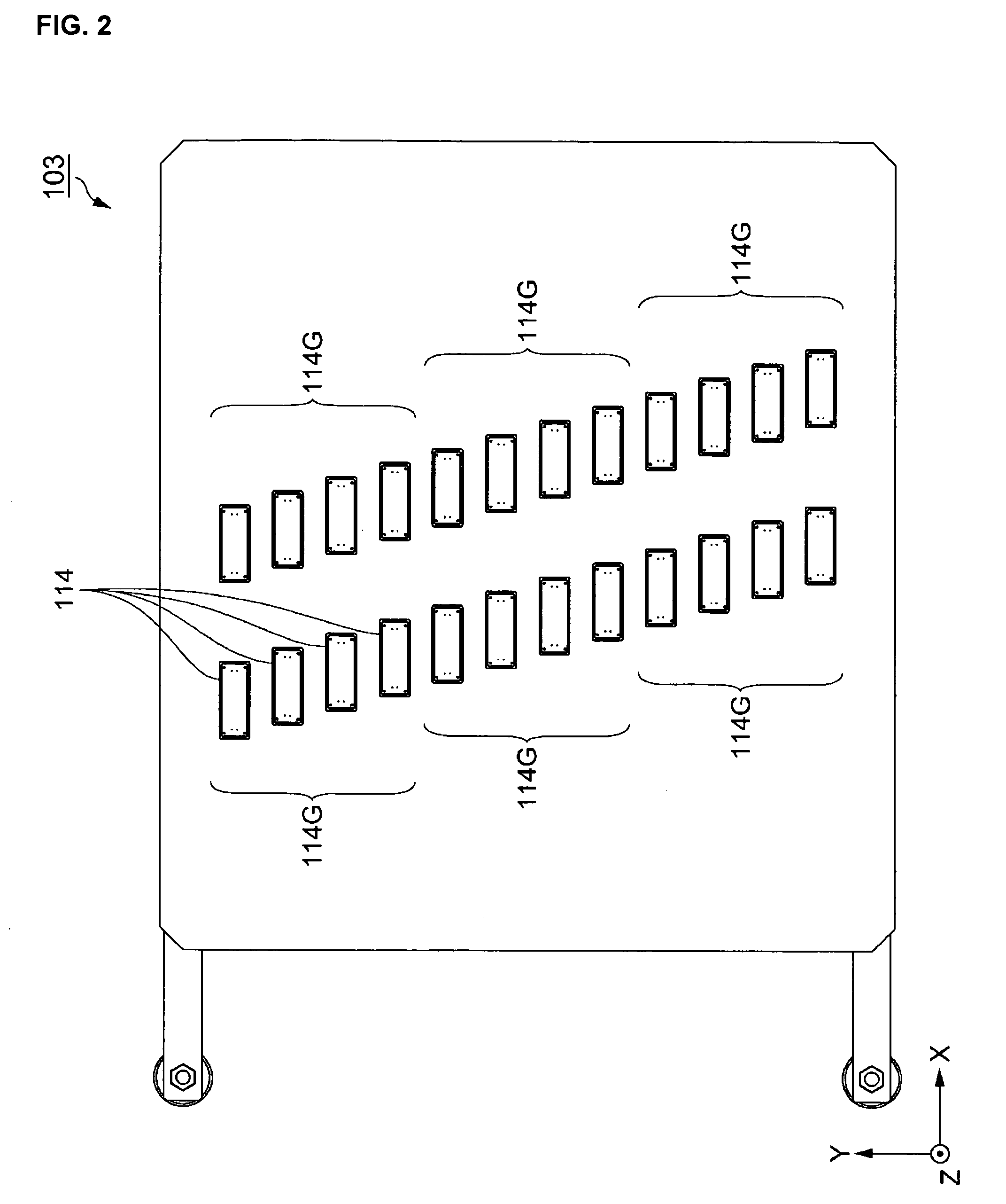
[0063]B. Carriage
[0064]C. Head
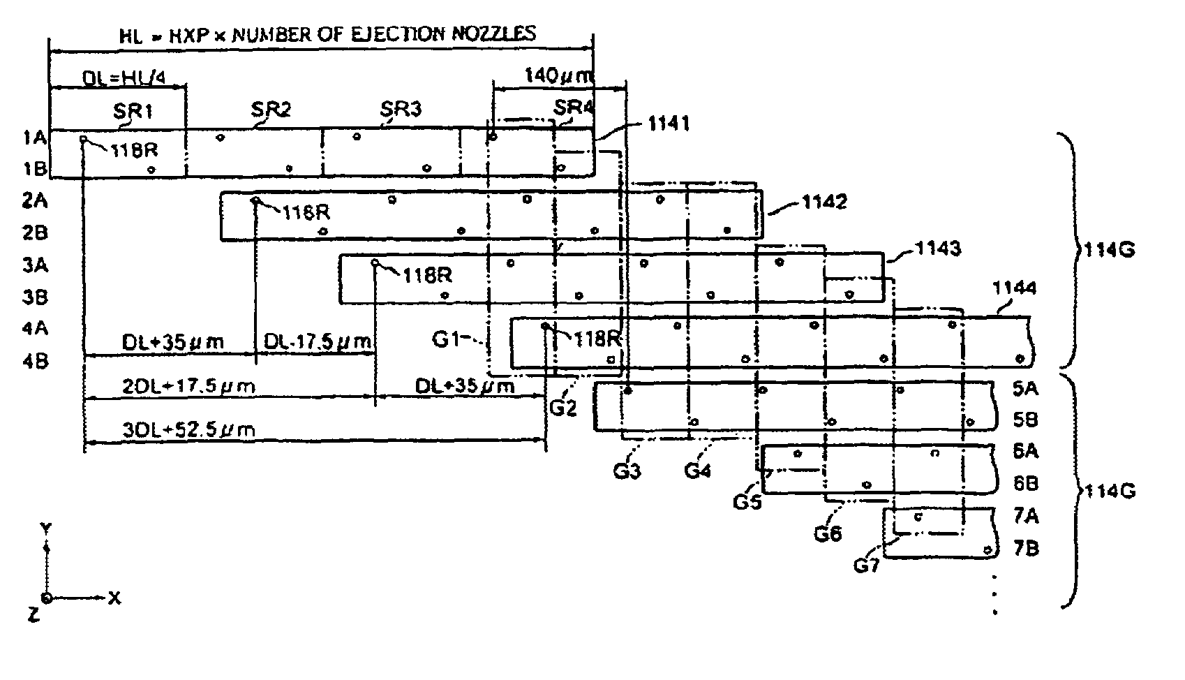
[0065]D. Head Group
[0066]E. Control Unit
[0067]F. Example of Ejection Method
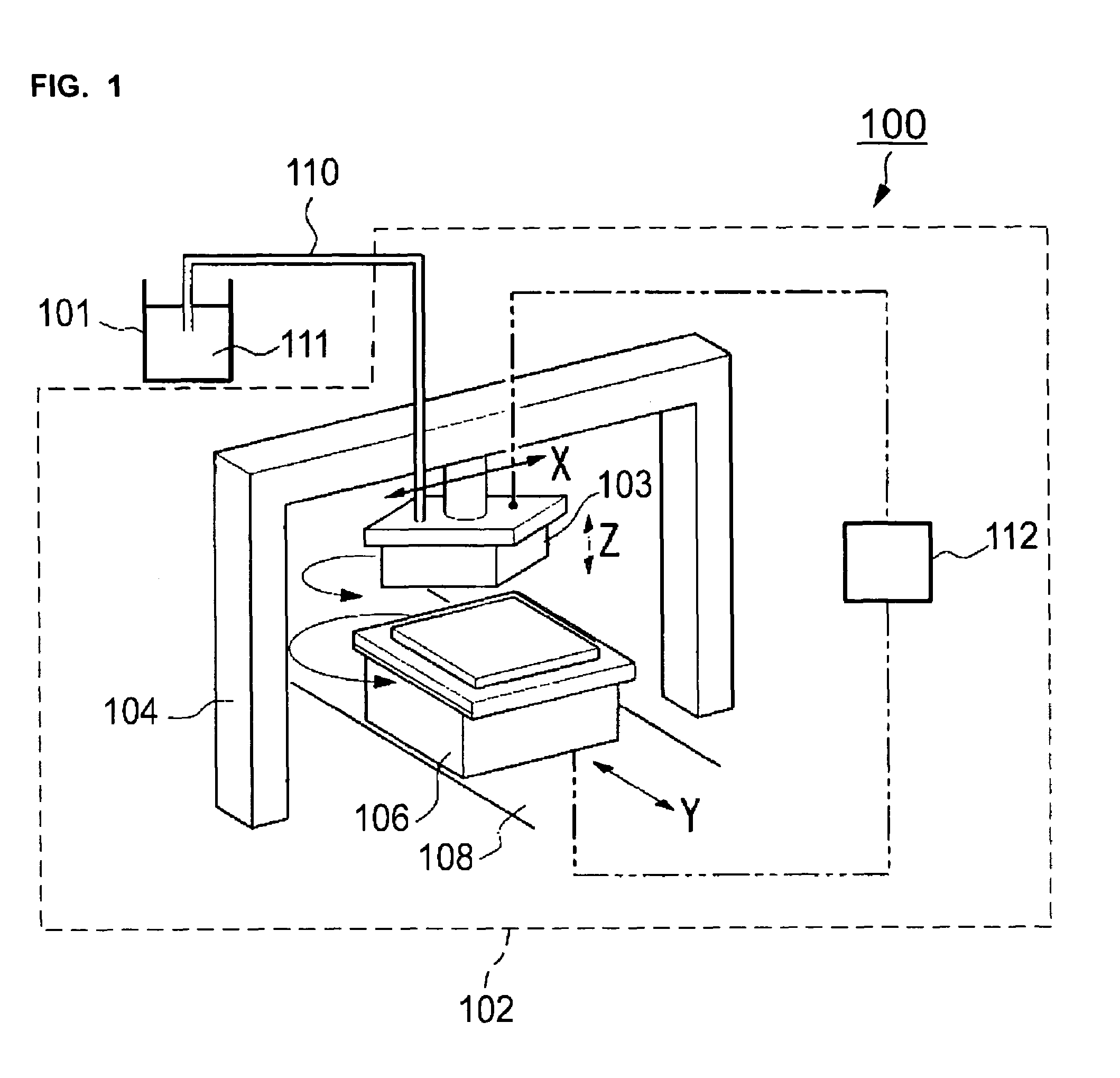
[0068]A. Entire Construction of Ejection Device
[0069]As shown in FIG. 1, an ejection device 100 comprises a tank for storing a liquid material 111, a tube 110, and an ejection scan unit 102 to which the liquid material 111 is supplied from the tank 101 via the tube 110. The ejection scan unit 102 comprises a carriage 103 for holding a plurality of heads 114 (FIG. 2), first position control means 104 for controlling a position of the carriage 103, a stage 106 for holding a base 10A, second position control means 108 for controlling a position of the stage 106, and a control unit 112. The tank 101 is connected to the plurality of heads 114 in the carriage 103 via the tube 110, such tha...
second embodiment
[0154]An example in which the present invention is applied to a manufacturing device of a color filter substrate will be described.
[0155]The base 10A shown in FIGS. 9(a) and 9(b) is a substrate which undergoes a process by a manufacturing device 1 (FIG. 10) described below and constitutes the color filter substrate 10. The base 10A has a plurality of portions to be ejected 18R, 18G and 18B which are arranged in a matrix shape.
[0156]More specifically, the base 10A comprises a light transmissive supporting substrate 12, black matrices 14 formed on the supporting substrate 12, and banks 16 formed on the black matrix 14. The black matrices 14 are made of a light-shielding material. And then, the black matrices 14 and the banks on the black matrices 14 are positioned to define a plurality of light transmissive portions in a matrix shape, that is, a plurality of pixel regions in a matrix shape, on the supporting substrate 12.
[0157]In the pixel regions, concave portions defined by the supp...
third embodiment
[0187]Next, an example in which the present invention is applied to a manufacturing device of an electroluminescent display device will be described.
[0188]The base 30A shown in FIGS. 14(a) and 14(b) is a substrate which becomes an electroluminescent display device 30 by means of a process with a manufacturing device 2 (FIG. 15) described below. The base 30A has a plurality of portions to be ejected 38R, 38G and 38B arranged in a matrix shape.
[0189]More specifically, the base 30A comprises a supporting substrate 32, a circuit element layer 34 formed on the supporting substrate 32, a plurality of pixel electrodes 36 formed on the circuit element layer 34, and banks 40 formed between the plurality of pixel electrodes 36. The supporting substrate is a substrate having light transmittance to visible light, for example, a glass substrate. Each of the plurality of pixel electrodes 36 is an electrode having light transmittance to visible light, for example, an ITO (Indium-Tin Oxide) electro...
PUM
| Property | Measurement | Unit |
|---|---|---|
| half length | aaaaa | aaaaa |
| length | aaaaa | aaaaa |
| volume | aaaaa | aaaaa |
Abstract
Description
Claims
Application Information