Recording adjustment device, recording adjustment method, and program

a technology of which is applied in the field of recording adjustment device and recording adjustment method, and the field of program, can solve the problems of data not being properly reproduced and the position shift of recorded marks

Active Publication Date: 2018-11-15
SONY CORP
View PDF0 Cites 3 Cited by
  • Summary
  • Abstract
  • Description
  • Claims
  • Application Information

AI Technical Summary

Benefits of technology

[0013]According to the present technique, the recording compensation for the optical disc for the high-linear density can be realized.
[0014]It should be noted that the effect described herein is not necessarily limited, and any of the effects described in the present disclosure may be offered.

Problems solved by technology

Such a thermal interference causes the position shift in the recorded mark.
In the case where the optical disc in which the mark position is shifted is subjected to the reproduction, the regenerative signal is influenced, so that the data cannot be properly reproduced.

Method used


Image

  • Recording adjustment device, recording adjustment method, and program
  • Recording adjustment device, recording adjustment method, and program
  • Recording adjustment device, recording adjustment method, and program

Examples


Embodiment Construction

of configuration of signal processing portion

[0042]2-3. Example 2 of configuration of signal processing portion

[0043]2-4. Recording adjustment processing of recording adjustment device

3. With Respect to Recording Strategy

4. Simulation Results

[0044]4-1. Influence of correction coefficient α

[0045]4-2. Change in amplitude difference average value

[0046]4-3. Change in binary jitter value

[0047]4-4. Effects

5. Modified Changes 1. Premise

[0048]

[0049]Firstly, a description will be given with respect to terms and notations which will be used hereinafter.

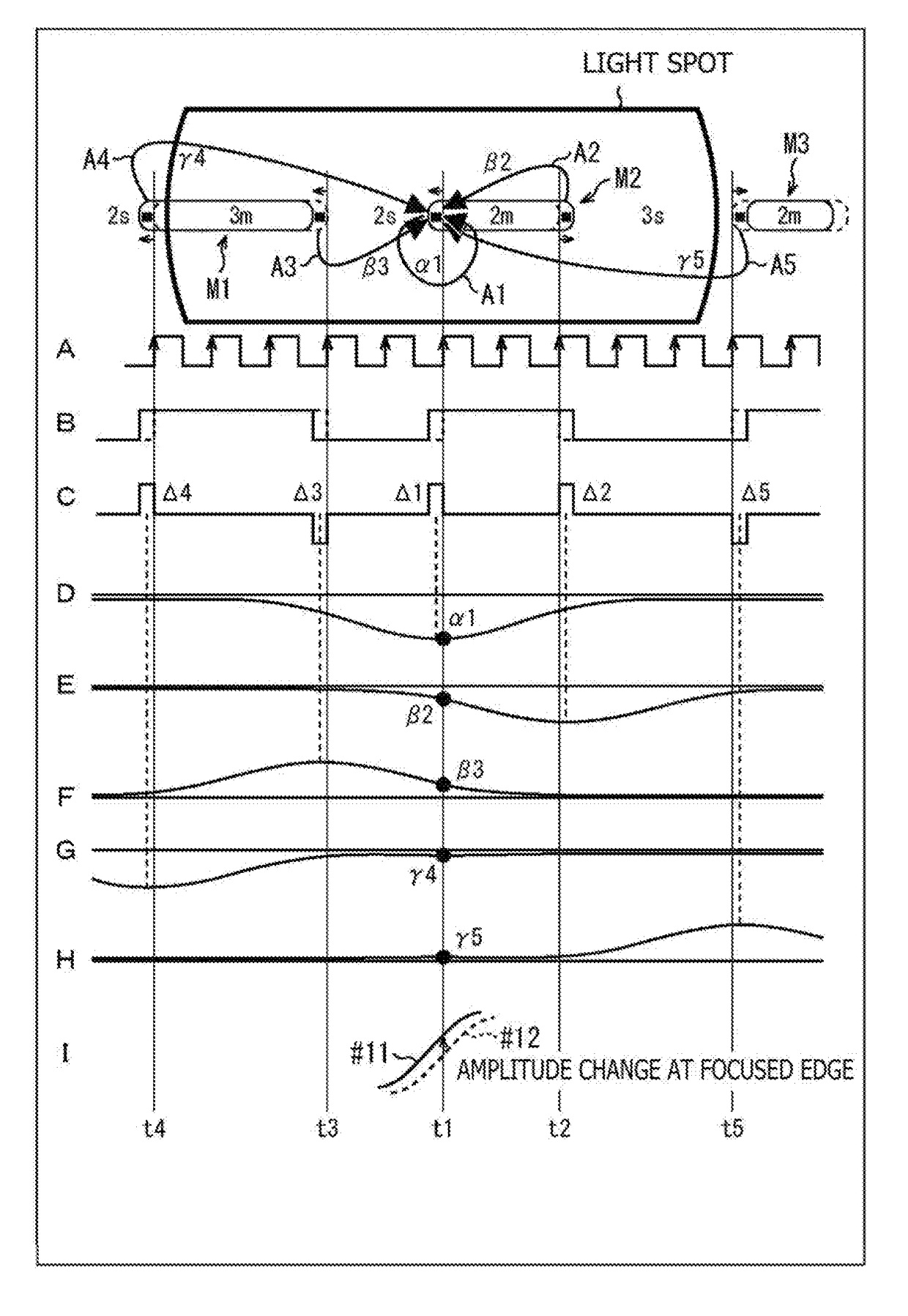
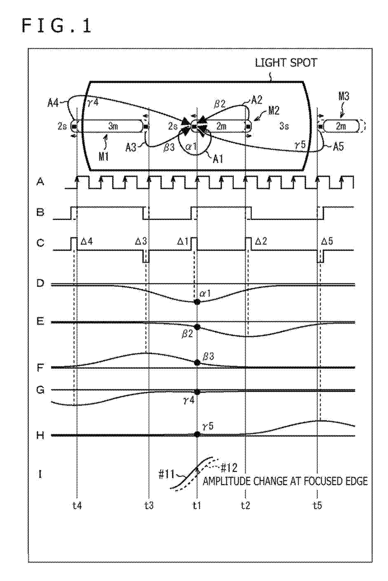
[0050]An “amplitude difference” represents a difference between an amplitude of a regenerative signal followed by edge shift, and an amplitude of a regenerative signal not followed by the edge shift. The regenerative signal followed by the edge shift is a regenerative signal obtained by reproducing recording data containing the edge shift. On the other hand, the regenerative signal not followed by the edge shift is an expected waveform. The exp...


PUM

PropertyMeasurementUnit
lengthaaaaaaaaaa
lengthaaaaaaaaaa
lengthaaaaaaaaaa

Abstract

There is provided a recording adjustment device, a recording adjustment method, and a program of which enables recording compensation for an optical disc for a high-linear density to be realized. The recording adjustment device according to an embodiment of the present technique executes filter processing on the basis of a regenerative signal obtained by reproducing data recorded in a recording medium, and a recording pattern of marks and spaces of the data, identifies an impulse response of a system, calculates a difference in amplitude between an output from the filter processing after the identification of the impulse response and the regenerative signal every edge type, and detects a slope of a step response in the vicinity of an edge position.

Description

TECHNICAL FIELD[0001]The present technique relates to a recording adjustment device, a recording adjustment method, and a program, and more specifically, to a recording adjustment device, a recording adjustment method, and a program of which enables recording compensation for an optical disc for a high-linear density to be realized.BACKGROUND ART[0002]In recent years, a use application as a medium for data archive for preserving important data in the long term has attracted attention as a use application of an optical disc such as a Blu-ray (registered trademark) Disc (hereinafter referred to as a BD). The higher-linear density promotion is required for the optical disc for data archive in order to enable the more data to be preserved.[0003]The recording of the data in the optical disc is carried out by forming a mark and a space in a recording layer. The intensity of a laser beam is modulated on the basis of a recording pattern, and the recording layer is irradiated with a recordin...

Claims


Application Information

Patent Timeline
Patent Type & Authority Applications(United States)
IPC IPC(8): G11B7/0045G11B20/10
CPCG11B7/00456G11B20/10046G11B20/10407G11B2220/2541G11B7/0045G11B20/10462G11B7/00
Inventor FUJIKI, TOSHIHIRO
Owner SONY CORP
Why Eureka
Try Eureka