Lancet device

Inactive Publication Date: 2005-09-27
SCHRAGA STEVEN
View PDF121 Cites 155 Cited by
  • Summary
  • Abstract
  • Description
  • Claims
  • Application Information

AI Technical Summary

Benefits of technology

[0017]Also an object of the present invention is to provide a lancet device which can be adjusted to two or more variable lengths, as need by the user and depending upon the number of extension segments utilized by the user, while still being fully operable.
[0018]A further object of the present invention is to provide a lancet device which can be configured in a mini configuration, yet which is highly effective and free from malfunction.
[0019]Yet another object of the present invention is to provide a lancet device which provides for substantially easy to recognize, tactile and/or visual indication if the lancet device is in a cocked and ready to fire orientation, or if it is in the

Problems solved by technology

The field of art associated with lancet devices is quite crowded, with a variety of often complex and intricate structures being utilized to drive a piercing tip of a lancet into the flesh of a patent.
In particular, a primary drawback associated with the mini lancet devices relates to its limited internal space, and as such, its inability to utilize various existing design features associated with the larger, full-size devices.
For example, known mini devices have not been able to utilize or incorporate a safe and effective structure to enable facilitated cocking or re-cocking of the lancet device.
Moreover, existing devices, both full-size and mini have not been able to provide eff

Method used


Image

  • Lancet device
  • Lancet device
  • Lancet device

Examples


Embodiment Construction

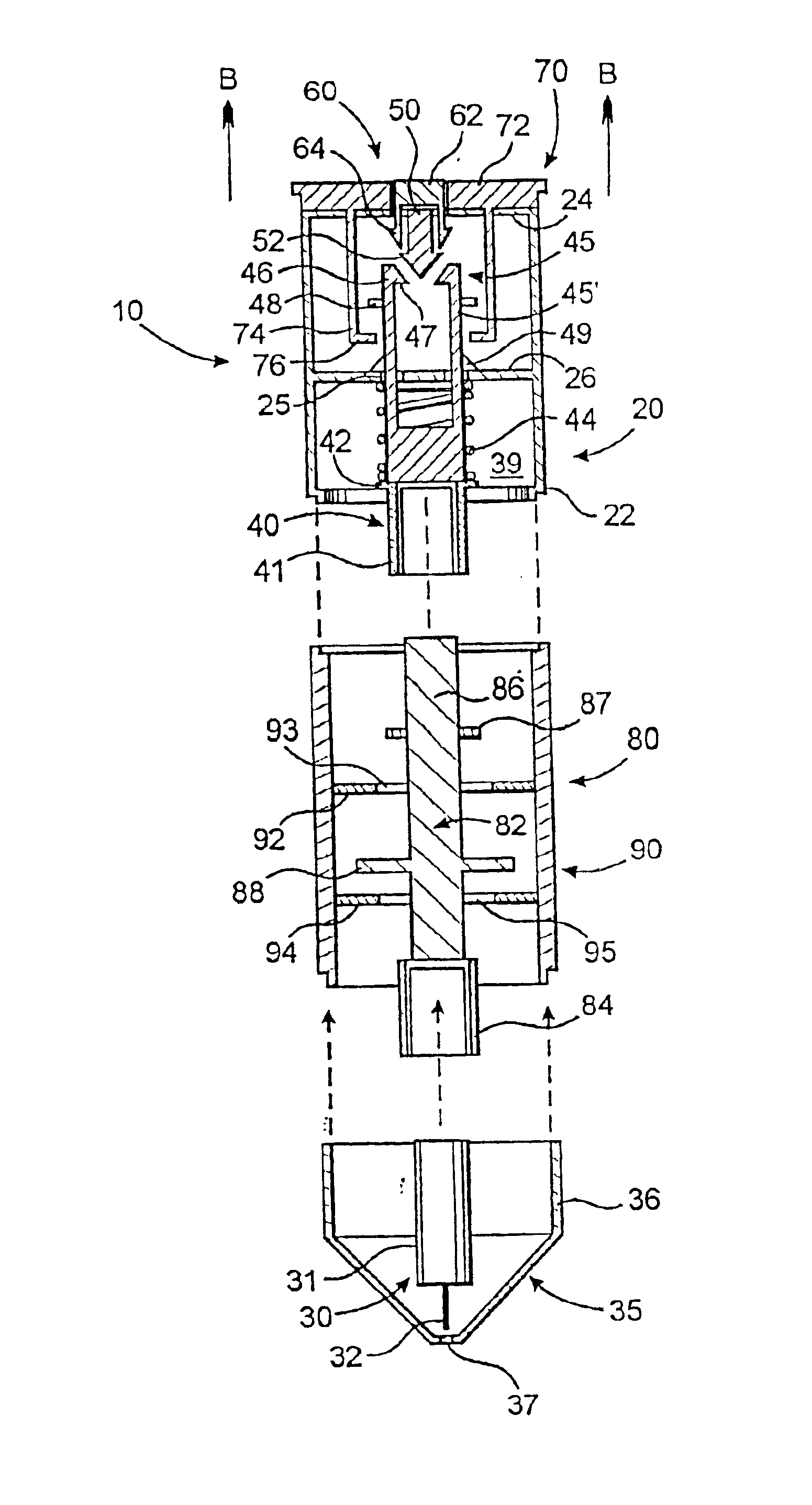
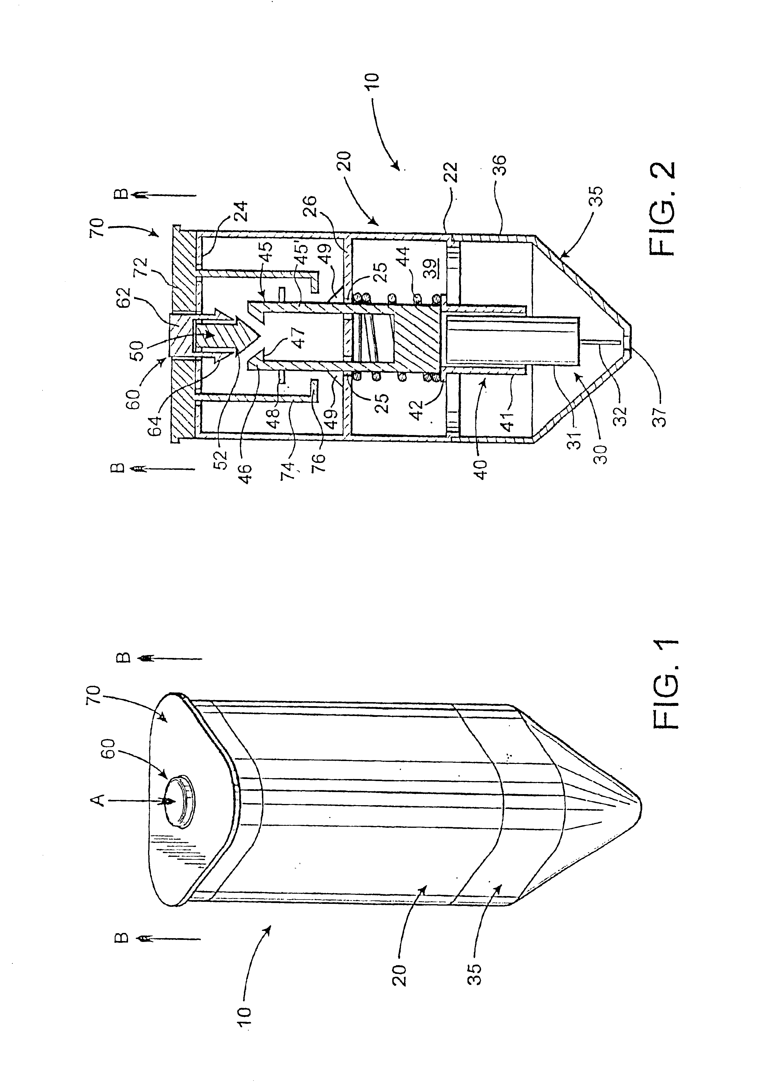
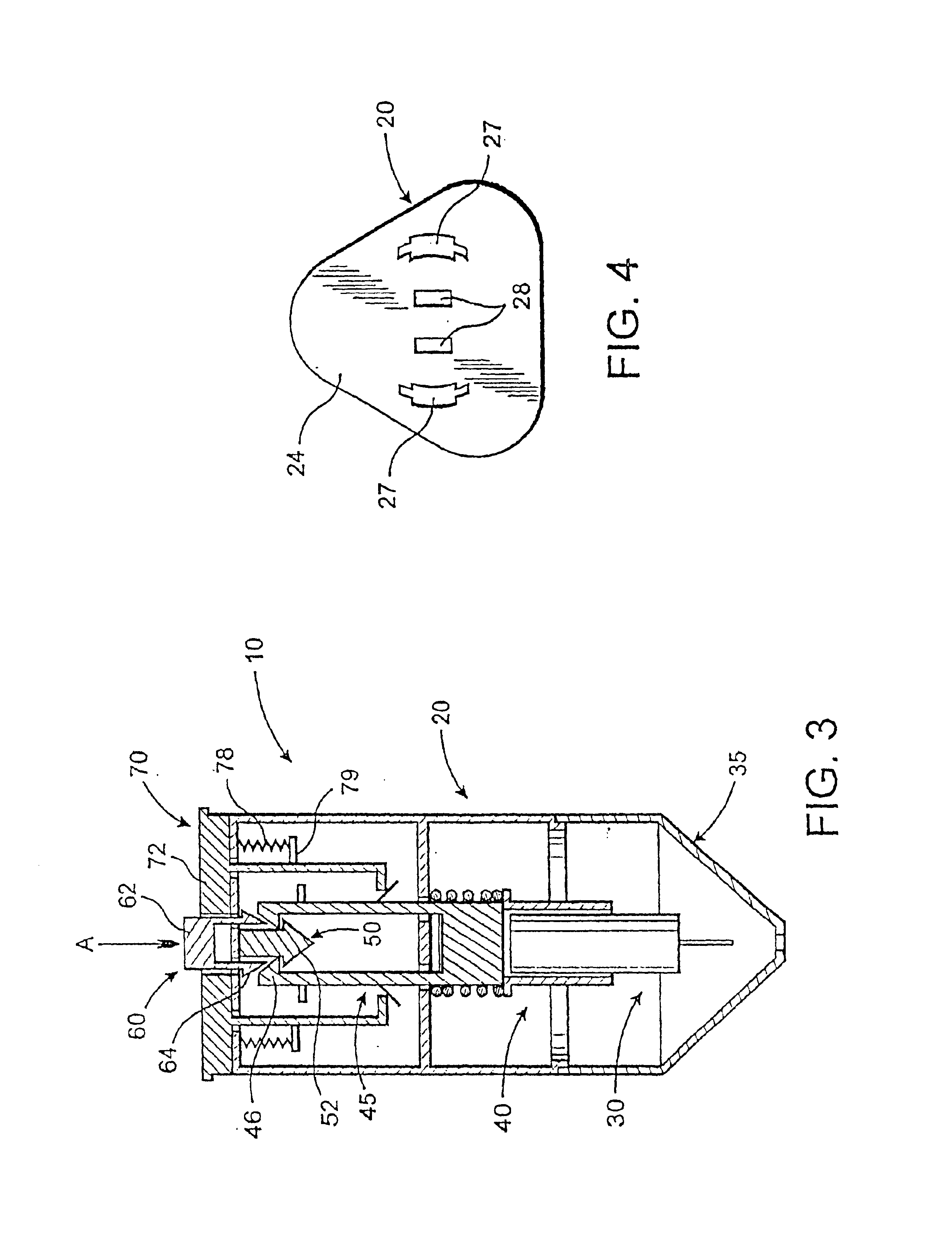
[0032]Shown throughout the Figures, the present invention is directed towards a lancet device, generally indicated as 10. Specifically, the lancet device is preferably of substantially small compact configuration, thereby being generally classified as a mini lancet device, and is of the type that is utilized to prick a patient, such as on their finger, in order to do a variety of blood tests.

[0033]The lancet device 10 of the present invention includes principally a lancet 30. The lancet 30 may be of any of a number of conventional or modified configurations which are usually provided in large bulk packages in order to encourage a single use after which it may be safely discarded. In particular, the lancet 30 generally includes a body portion 31, preferably of an enlarged, tubular configuration, and a sharpened, preferably metallic piercing tip 32 extending from the body portion 31. Also, in most embodiments, the piercing tip 32 will be covered by a removable and disposable cap which...


PUM


Abstract

A lancet device used to pierce a user's skin and including a lancet with a body portion and a piercing tip, a primary housing, a cover assembly with a piercing opening and structured to be matingly coupled with the primary housing to define an interior chamber, and a lancet receiving assembly movably disposed within the interior chamber and structured and disposed to hold the lancet during its driven movement between a cocked orientation, a piercing orientation and a fired orientation. The lancet device further includes a retention member including a pair of elongate fingers, and an engagement hub disposed in the interior chamber and structured to be cooperatively engaged by inwardly depending protrusions on the elongate fingers when the lancet receiving assembly is in the cocked orientation so as to maintain the lancet receiving assembly in the cocked orientation until the retention member is affirmatively released from its cooperative engagement with the engagement hub by an exteriorly actuatable actuation assembly which urges the elongate fingers out of their engagement with cooperative structure on the engagement hub. Moreover, a removable extension segment is preferably provided so as to increase an overall length of the lancet device as desired by a user.

Description

CLAIM OF PRIORITY[0001]The present application is a Continuation-In-Part application of previously filed, now pending application having Ser. No. 09 / 296,346 which was filed on Apr. 22, 1999 which matured into U.S. Pat. No. 6,190,398 on Feb. 20, 2001, which is a Continuation-In-Part of United States patent application having Ser. No. 09 / 025,292 filed Feb. 13, 1998, also incorporated herein by reference, which matured into U.S. Pat. No. 5,908,434 Jun. 1, 1999.BACKGROUND OF THE INVENTION[0002]1. Field of the Invention[0003]The present invention relates to a lancet device, and in particular a mini lancet device which is structured in such a manner as to be manufacturable in a small, compact configuration, yet which is substantially easy to use and is effective to pierce a user's skin, such as at a finger for conducting a blood test. Furthermore, the lancet device is easy to manipulate and actuate, is structured in a manner which facilitates accurate determination that the device is in a...

Claims


Application Information

Patent Timeline
IPC IPC(8): A61B5/15
CPCA61B5/1411A61B5/150022A61B5/150267A61B5/15113A61B5/15117A61B5/15194A61B5/150412
Inventor SCHRAGA, STEVEN
Owner SCHRAGA STEVEN
Why Eureka
Try Eureka