Collision energy absorbing structure of vehicle

a technology of energy absorption structure and collision energy, which is applied in the direction of pedestrian/occupant safety arrangement, bumpers, elastic dampers, etc., can solve the problems of complex structure and difficult to obtain stable energy absorption characteristics, and achieve the effect of low cost and easy manufactur

Inactive Publication Date: 2005-10-04
KAWASAKI HEAVY IND LTD
View PDF18 Cites 15 Cited by
  • Summary
  • Abstract
  • Description
  • Claims
  • Application Information

AI Technical Summary

Benefits of technology

[0015]The present invention addresses the above-described condition, and an object of the present invention is to provide a collision energy absorbing structure of a vehicle capable of absorbing impact by using a tubular pipe member having an equally-sized rectangular cross section and an equal plate thickness and including no inside ribs and by adding a suitable trigger, and being easily manufactured at a low cost.
[0017]According to the present invention, the strength of the deformation staring portion is lower than the strength of the other part of the energy absorbing member and the initial impact force can be reduced. In addition, since the deformation starting portion is provided by reducing the size of part of the tubular energy absorbing member with rectangular cross section, the structure can be simplified.
[0021]Since the front end portion (extended portion) has already started to be deformed, the following tubular portion starts to be deformed like bellows naturally. More specifically, the deformation sequentially occurs in the front end portion (extended portion) and the portion continuous with the front end portion, while the portion provided with the cutout portion starts to be newly deformed like bellows after the bellows-like deformation of the front end portion, so that the force peak for generating the new bellows-like deformation is reduced and the bellows-like deformation naturally takes place. Consequently, the collision energy can be efficiently absorbed.
[0022]Further, since the tubular pipe with rectangular cross section is provided with the cutout portion, that is, the channel-shaped extended portion, the energy absorbing member can be manufactured easily and at a low cost. In particular, since the front end portion is provided with the cutout portion, i.e., the extended portion so as to be vertically or laterally asymmetric, the reaction force in the initial stage of collision can be reduced with such simple structure. Also, since the bellows-like deformation has already started in part (asymmetric portion) of the front end portion, the reaction force at the start of deformation of the other portion is reduced to be substantially equal to the reaction force in the initial stage of the collision (see FIG. 2), thereby keeping a constant reaction force. Consequently, the impact acting on the passengers can be relieved without a rapid rise in the impact force.
[0025]The collision energy absorbing structure may further comprise: a rubber damper connected to a coupler of the vehicle, for absorbing and relieving impact generated between vehicles, and a front end portion of the energy absorbing member may be connected to a rear end portion of the rubber damper and a rear end portion of the energy absorbing member may be connected to a draft stop mounted to a vehicle body frame.
[0030]In this constitution, since the energy absorbing member extending forwardly of the coupler in the front vehicle is provided with the collision member at the front end thereof, the collision member is collided and the collision energy is absorbed by the bellows-like deformation of the energy absorbing members. Consequently, the impact acting on the passengers can be relieved.

Problems solved by technology

However, the structures of (1)-(4) suffer from the following drawbacks.(A) In the structure disclosed in Japanese Patent No. 2650527, since the inclined portions are formed at the ribs inside of the member body, its structure is complicated.
Since the bellows-like deformation tends to be unstable in the cylindrical frame as compared to the tubular frame with rectangular cross section, a stable energy absorbing characteristic is difficult to obtain.(C) In the structures disclosed in Publications of Examined Patent Applications Nos. Hei. 11-5564, 9-277953, 9-277954, since the pipe member (side member or energy absorbing member) has a structure with the cross section varying in the axial direction thereof, a special and complicated process is needed.

Method used


Image

  • Collision energy absorbing structure of vehicle
  • Collision energy absorbing structure of vehicle
  • Collision energy absorbing structure of vehicle

Examples


example 1

[0069]In this example, the energy absorbing member is applied to a coupler of a railroad vehicle.

[0070]Referring to FIGS. 13, 14, a rubber damper 11 comprises a draft stop 12 having a front support portion 12a and a rear support portion 12b, front and rear impact absorbing rubbers 13a, 13b respectively provided in the front support portion 12a and the rear support portion 12b of the draft stop 12, a pair of connecting rod members 14R, 14L for respectively connecting and fixing the impact absorbing rubbers 13a, 13b (rubber plates) to the draft stop 12, and flange members 15a, 15b respectively mounted to a front portion of the connecting rod member 14R and a rear portion of the connecting rod member 14L and interposing the impact absorbing rubbers 13a, 13b in the draft stop 12. The front end portions of the connecting rod members 14L, 14R are connected to a front support frame 16F, which is connected to a rear end portion of a coupler 18 with an intermediate member 17 interposed there...

example 2

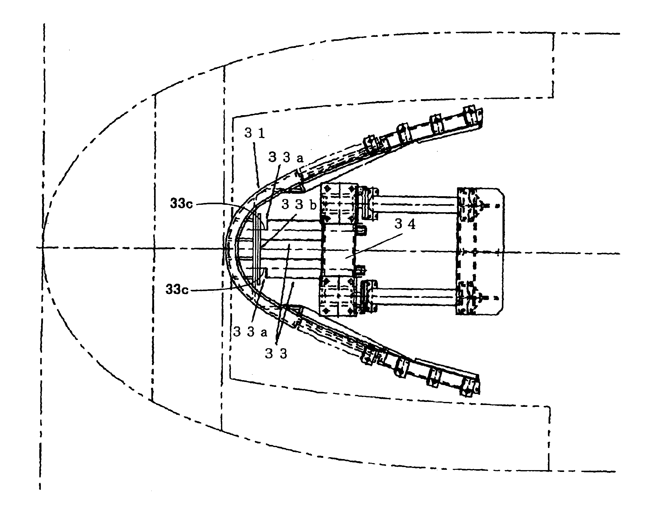
[0073]In this example, the energy absorbing member is applied to a rail guard of a front vehicle of a railroad vehicle.

[0074]Referring to FIGS. 15, 16, a rail guard board 31 for eliminating obstacles is bent like horseshoe and mounted and fixed to a vehicle body frame 32. Two energy absorbing pipe members 33 are placed behind the rail guard board 31 so as to be spaced apart therefrom. These energy absorbing pipe members 33 are coupled by means of a coupling member 33b and supported by a support device 34. More specifically, the flat-plate shaped coupling member 33b is connected to tip ends of the respective energy absorbing pipe members 33 and rear ends of the members 33 are fixed to the support device 34. An upper end portion of the support device 34 is fixed to the vehicle body frame 32. In this case, the cutout portions 33a of the respective energy absorbing pipe members 33 are opened outwardly (or inwardly) and laterally symmetric as shown in FIG. 16. In other words, the energy ...

example 3

[0077]In this example, the impact absorbing member is mounted to the front portion of the front vehicle of the railroad vehicle to absorb the collision energy when front vehicles head-on collide.

[0078]Referring to FIGS. 17, 18, an energy absorbing pipe member 43 is provided between a coupler 41 located on an upper side and a rail guard plate 42 located on a lower side in the vertical direction. A support pipe member 45 is provided so as to extend in the longitudinal direction of the vehicle from a support device 44 and a rear end portion of the energy absorbing pipe member 43 provided with a tip member 46 is connected to a tip end portion of the support pipe member 45.

[0079]The support pipe member 45 extends forwardly of the rail guard board 42 and has a length so as to be located behind the coupler 41. When the vehicle is not used as the front vehicle, the energy absorbing pipe member 43 is removed from the vehicle to allow vehicles to be interconnected by means of the coupler 41. ...


PUM


Abstract

Disclosed is a collision energy absorbing structure of a vehicle capable of relieving impact by using a tubular pipe member having equally-sized rectangular cross section and equal plate thickness and including no inside ribs and by adding a suitable trigger, and being easily manufactured at a low cost. By forming a cutout portion on the left side of the front end portion of the collision energy absorbing structure, the deformation starting portion is provided. The cutout portion is formed at parts of three flat plate portions comprised of one of the four flat plate portions and corresponding opposite portions thereof. The general portion, which follows the deformation starting portion, is tubular with rectangular cross section and has a closed cross-section structure.

Description

CROSS REFERENCE TO RELATED APPLICATION[0001]The present application is a divisional patent application of U.S. patent application Ser. No. 10 / 116,604 filed on Apr. 4, 2002.BACKGROUND OF THE INVENTION[0002]1. Field of the Invention[0003]The present invention relates to a collision energy absorbing structure of a vehicle which is used for absorbing a collision energy generated by a collision of vehicles such as railroad vehicles by bellows-like deformation (plastic deformation) of a tubular energy absorbing member with rectangular cross section to relieve impact when collision occurs.[0004]2. Description of the Related Art[0005]In general, it is known that a pipe member can be used as an energy absorbing member for absorbing a collision energy by bellows-like deformation, because the pipe member is plastically deformed like bellows while suppressing deformation of the Euler buckling when a compression force is axially applied to the pipe member by suitably selecting a dimension or a t...

Claims


Application Information

Patent Timeline
Patent Type & Authority Patents(United States)
IPC IPC(8): B62D21/15B61D15/00B61D15/06B60R19/24B60R19/34F16F7/12B60R21/02B61F1/10B61F19/04B61G11/10B61G11/16
CPCB60R19/34B61D15/06B62D21/15F16F7/12
Inventor TAGUCHI, MAKOTO
Owner KAWASAKI HEAVY IND LTD
Why Eureka
Try Eureka