
Walking support having shoehorn/gripper and magnet accessories

a technology of walking support and magnet accessories, which is applied in the direction of gripping heads, load-engaging elements, borehole/well accessories, etc., and can solve the problems of causing considerable inconvenience in removal

Inactive Publication Date: 2005-10-04
GARRETT MELVIN C
View PDF29 Cites 29 Cited by
  • Summary
  • Abstract
  • Description
  • Claims
  • Application Information

AI Technical Summary

Benefits of technology

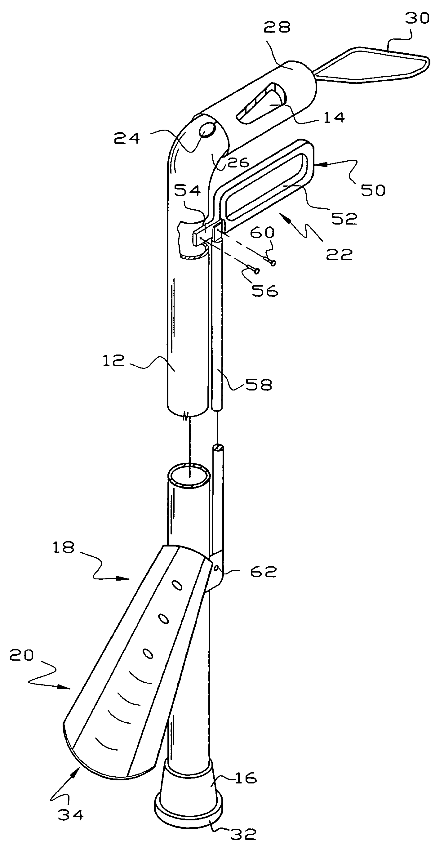
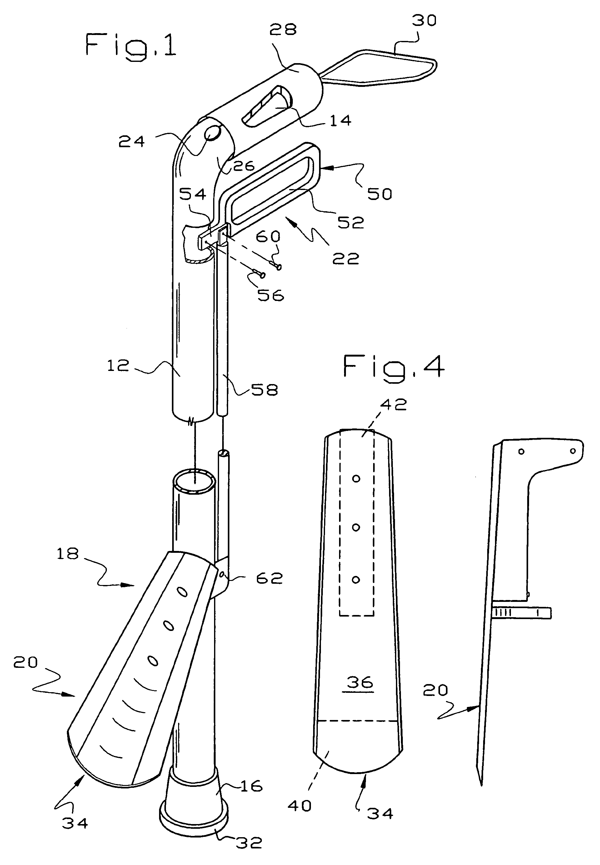
[0005]In this invention, a walking stick or walking support provides a variety of functions in addition to assisting the user to walk or otherwise partially supporting the weight of a user. A shoehorn assembly is pivotally mounted adjacent the foot of the walking stick to assist the user in putting on shoes and to provide a gripping device to pick objects off a remote surface. An actuator for moving the shoehorn includes a supplementary handle or trigger adjacent the main hand support of the walking stick. A permanent magnet is provided on the handle of the walking stick so the walking stick may be inverted and pick magnetizable objects off a remote surface. Placing the magnet on the handle keeps the magnet free of debris which would be picked up off the floor during normal use of the walking stick.
[0007]A further object of this invention is to provide an improved walking stick which has the capability of assisting the user to put on shoes and to grip objects distant from the user.
[0008]Another object of this invention is to provide an improved walking stick having a magnet on the handle to assist picking up magnetic objects distant from the user.
[0009]Another object of this invention is to provide a walking stick having the ability to assist the user to pick up objects from the floor either magnetically or by gripping the object.

Problems solved by technology

The difficulty with permanent magnets in the foot of walking sticks is that magnetizable debris on the floor inadvertently collects on the foot during normal use and is a considerable inconvenience to remove.

Method used


Image

  • Walking support having shoehorn/gripper and magnet accessories
  • Walking support having shoehorn/gripper and magnet accessories
  • Walking support having shoehorn/gripper and magnet accessories

Examples


Embodiment Construction

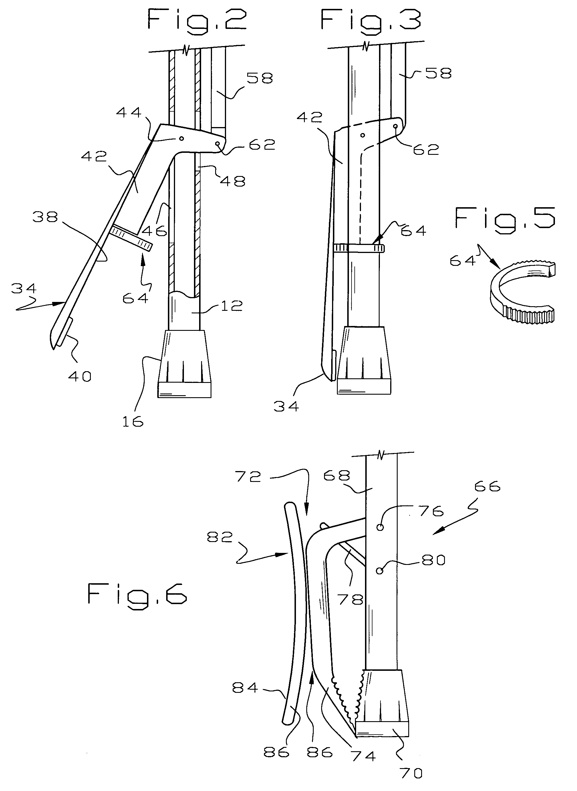
[0017]Referring to FIGS. 1–5, a walking stick walking support or cane 10 of this invention comprises, as major components, a sturdy elongate support 12 having a hand support or handle 14 at one end and a foot 16 at the other, a gripper 18 including a shoehorn assembly 20 and a mechanism 22 for moving the shoehorn assembly 20 toward and away from the foot 16, and a magnet 24 for picking up magnetizable objects.

[0018]The support 12 and handle 14 may be made of any suitably sturdy material and preferably are made from a non-corrodible metal tube. The support 12 may be made in a variety of lengths to accommodate people of different height. In the alternative, the support 12 may be of adjustable length, as explained more fully hereinafter. The handle 14 may be of any desired configuration and is illustrated as being of a conventional cane-like type, being generally perpendicular to the support 12 and connected to the support 12 by a suitable smooth bend 26. Conveniently, a resilient cove...


PUM


Abstract

A walking stick or cane comprises a support having a foot at one end thereof and a handle at the other. A gripper device adjacent the foot includes a shoehorn assembly pivoted to the support for movement toward and away from the foot for grasping objects between the end of the foot and the shoehorn assembly. The gripper device is operated by a trigger mounted adjacent the handle and a rod generally parallel to the support. In one embodiment, the shoehorn assembly includes a shoehorn which acts to grasp an object. In another embodiment, the shoehorn assembly includes a shoehorn which does not act to grasp an object. A permanent magnet on the handle allows the user to invert the cane and pick up iron objects. Because the magnet is adjacent the handle, it does not collect floor debris during normal use.

Description

[0001]This invention relates to an improved walking stick or cane having multiple capabilities thereby providing a more functional and desirable walking stick.BACKGROUND OF THE INVENTION[0002]Those who use a walking stick or cane often find themselves in a situation where it is necessary or desirable to perform some function at a location remote from the user's hands. For example, putting on shoes requires an unassisted user to bend over and slip a foot into the shoe, using one hand to manipulate the edge of the shoe so the foot slips inside. Shoehorns have long been known to assist putting on shoes and long handled shoehorns are known to avoid bending over. Shoehorns are also known to be incorporated in walking sticks as shown in U.S. Pat. Nos. 4,966,316 and 5,392,800. Other disclosures of combined shoehorn / gripper devices are found in U.S. Pat. Nos. 3,591,226 and 4,709,839.[0003]Another example of a situation where a walking stick user finds it desirable to perform some function a...

Claims


Application Information

Patent Timeline
Patent Type & Authority Patents(United States)
IPC IPC(8): A45B3/00A45B7/00
CPCA45B3/00A45B7/005
Inventor GARRETT, MELVIN C.
Owner GARRETT MELVIN C
Learn More