Shaft seal with elastic sealing lip

a technology of sealing lip and shaft, applied in the direction of engine sealing, leakage prevention, machines/engines, etc., can solve the problems of high cost, high cost, and high damage of combination of low ph and high temperatur

Inactive Publication Date: 2005-10-04
VALMET TECH INC
View PDF13 Cites 1 Cited by
  • Summary
  • Abstract
  • Description
  • Claims
  • Application Information

AI Technical Summary

Problems solved by technology

In connection with such means there is the problem that the V-ring is destroyed and requires frequent exchange.
This causes very expensive shutdowns.
The combination of low pH and high temperature i...

Method used


Image

  • Shaft seal with elastic sealing lip
  • Shaft seal with elastic sealing lip

Examples


Embodiment Construction

[0023]The dewatering means, as such, will not be described in detail, because it is already well known, such as through the specifications referred to above.

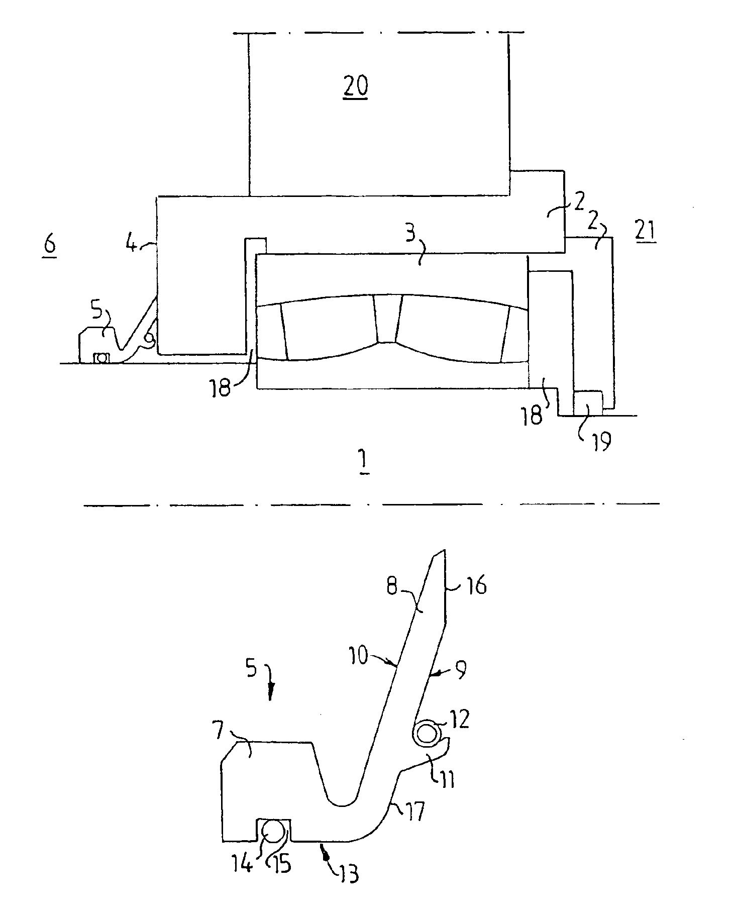
[0024]FIG. 1 shows a portion of a shaft in a dewatering means of the type described above. Only the upper half of a shaft 1 is shown, because the means is substantially symmetric.

[0025]In a bearing housing 2 on the shaft 1 a bearing 3 is located. The bearing housing 2 is located in a hole in a wall 20, which separates a medium space 6 from the outside of the dewatering means, i.e. the atmosphere 21.

[0026]The medium space 6 contains the filtrate, which by means of the dewatering means was pressed out of a pulp suspension. The filtrate contains also a certain amount of fibers, which at the dewatering followed along with the filtrate.

[0027]The bearing housing, together with the shaft, encases a bearing space 18, in which the bearing 3 is located. The bearing space 18 suitably is filled with oil, but can also, for example, be filled...


PUM


Abstract

A V-ring seal is disclosed for sealing between relatively rotatable surfaces in which the V-ring seal comprises PTFE and includes a body with an inner side for abutting against a first surface and a lip extending from the body towards a second surface, the lip including a rear side distal from the second surface, a front side proximate to the second surface, a lower portion proximate to the body, an upper portion distal from the body, a sealing surface on the front side of the lip for abutting the second surface to seal the second surface, and a resilient ring for providing a force acting on the lip to urge the sealing surface towards the second surface, the resilient ring being disposed on the front side of the lower portion of the lip whereby the resilient ring is concealed from the rear side of the lip.

Description

FIELD OF THE INVENTION[0001]The present invention relates to a sealing of the type V-ring.[0002]A V-ring can be used for sealing at a cylindric rotary cylindrical body. This cylindric body can be, for example, a shaft for a roll in a dewatering means for dewatering material suspensions. Such a dewatering means can comprise two co-acting cylindric rotary rolls, at least one of which is liquid permeable. The rolls form a nip between them, through which the material suspension is intended to pass, while simultaneously being dewatered. The material suspension usually passes through the nip upward from below.[0003]The material suspension can be, for example, a pulp suspension, and the dewatering means can thus be a washing press or a dewatering press.[0004]Dewatering means known in the art will be described below in which both rolls are liquid permeable. The rolls are formed with liquid permeable shell surfaces, which consist of a perforated metal sheet attached on a roll body.[0005]The ...

Claims


Application Information

Patent Timeline
IPC IPC(8): F16J15/16F16J15/34
CPCF16J15/164F16J15/3452F16J15/3456
Inventor LUNDBERG, JORGEN T
Owner VALMET TECH INC
Why Eureka
Try Eureka