
In-line mixing apparatus, process for mixing reactive chemical solutions, and process for producing microcapsules

a technology of reactive chemical solutions and mixing equipment, which is applied in chemical/physical/physical-chemical processes, rotary stirring mixers, transportation and packaging, etc., can solve the problems of liquid leakage from and shaft sealing portion or mechanical seal function deterioration

Inactive Publication Date: 2007-02-06
FUJIFILM CORP
View PDF12 Cites 0 Cited by
  • Summary
  • Abstract
  • Description
  • Claims
  • Application Information

AI Technical Summary

Benefits of technology

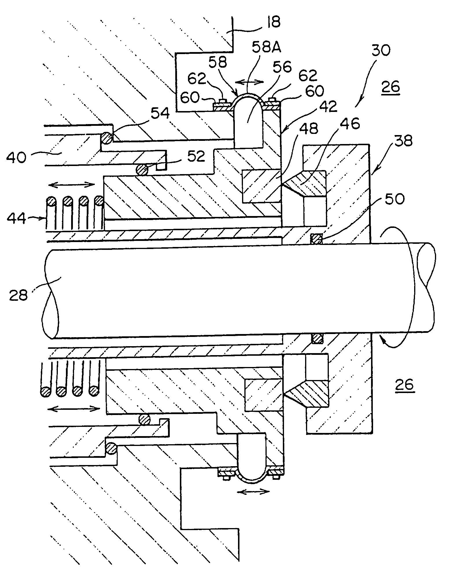
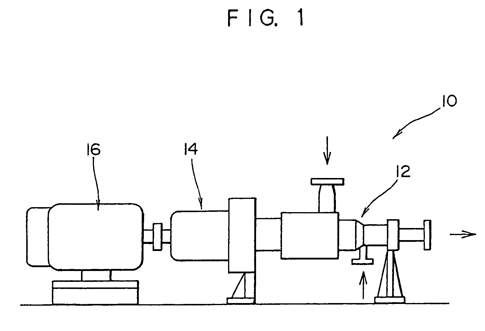
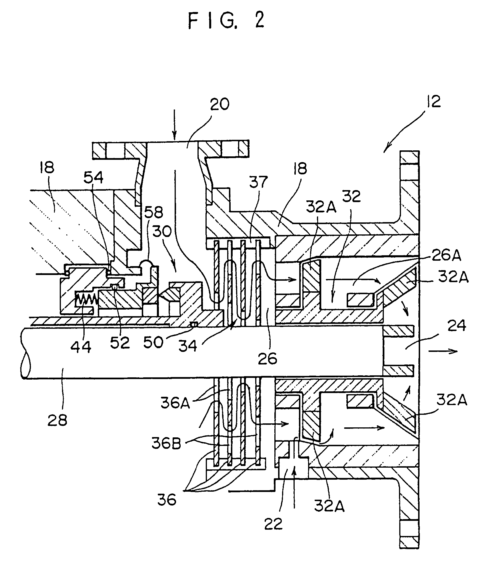
[0014]According to the invention, the chemical solution injected into the mixing flow path from the upstream inlet forms a flow from the upstream inlet to the discharge outlet on the mixing flow path, and the rotary blade provided at the downstream side of the shaft sealing portion or mechanical seal. The positional relationship of the flow and the rotary blade can make it difficult for the chemical solution injected into the mixing flow path from the downstream inlet, which is disposed at the downstream side of the shaft sealing portion or mechanical seal, to flow back toward the shaft sealing portion or mechanical seal even when turbulent flow occurs due to the rotation of the rotary blade. Therefore, when a reactive chemical solution is injected from the downstream inlet with respect to the shaft sealing portion or mechanical seal, even if a hard reaction product is formed by mixing of the chemical solutions, almost all of the reaction product does not reach the shaft sealing portion or mechanical seal but is discharged from the discharge outlet. Consequently, deterioration of the function of the shaft sealing portion or mechanical seal due to adhesion of the reaction product to the shaft sealing portion or mechanical seal is not liable to occur, and thus leakage of the liquid from the shaft sealing portion or mechanical seal can be effectively prevented. Thus, stable continuous mixing can be carried out over a long period of time even when chemical solutions having reactivity are mixed.
[0026]According to the aspect, even when an extremely hard reaction product of blackish brown color is formed through a reaction between the polyvalent isocyanate and the polyol, most of a hard reaction product does not reach the shaft sealing portion or mechanical seal but is discharged from the discharge outlet. Therefore, the reaction product can be prevented from adhering to and growing on the shaft sealing portion or mechanical seal.

Problems solved by technology

Consequently, the function of the shaft sealing portion or mechanical seal is deteriorated, causing such problems as leakage of the liquid from the shaft sealing portion or mechanical seal.
Furthermore, water, which is contained in the oil phase in trace amounts, reacts with the polyvalent isocyanate, and the resultant reaction product adheres to and develops on the shaft sealing portion or mechanical seal of the rotation shaft supporting agitation blades provided in the mixing flow path, so that the function of the shaft sealing portion or mechanical seal is deteriorated, causing such problems as leakage of the liquid from the shaft sealing portion or mechanical seal.
Particularly, in the case where the shaft sealing portion is a mechanical seal, when the reaction product is adhered on a pressing means for pressing a seal ring member to a rotation ring member, the pressing means cannot conform with vibrations caused by high speed rotation of the rotation ring member, and the pressing pressure of the seal ring member to the rotation ring member is decreased, causing leakage of the liquid.
Due to the problems described above, stable operation over a long period of time, which is an intrinsic advantage of continuous mixing by the in-line mixing apparatus, becomes difficult to carry out, and operation shutdown and disassembly for cleaning are necessary after an extremely short period of time.
Thus, a considerable reduction in production efficiency is caused.
The positional relationship of the flow and the rotary blade can make it difficult for the chemical solution injected into the mixing flow path from the downstream inlet, which is disposed at the downstream side of the shaft sealing portion or mechanical seal, to flow back toward the shaft sealing portion or mechanical seal even when turbulent flow occurs due to the rotation of the rotary blade.

Method used


Image

  • In-line mixing apparatus, process for mixing reactive chemical solutions, and process for producing microcapsules
  • In-line mixing apparatus, process for mixing reactive chemical solutions, and process for producing microcapsules
  • In-line mixing apparatus, process for mixing reactive chemical solutions, and process for producing microcapsules

Examples


example 1

[0057]An oil phase solution having 10 parts by weight of crystal violet lactone, 1 part by weight of benzoyl leuco methylene blue and 4 parts by weight of 3-(4-(diethylamino)-2-methoxy phenyl)-3-(2-methyl-1-ethyl-3-indolyl)-4-azaphthalide dissolved in this ratio therein as color formers was stored in a first storage tank at 65° C. As a polyvalent isocyanate, a biuret product of hexamethylenediisocyanate (Sumitomo N3200, produced by Sumitomo Bayer Urethane Co., Ltd.) was stored in a second storage tank at 30° C. As a polyol, HYBLOCKS ODX-1316A, produced by Dainippon Ink and Chemicals, Inc., was stored in a third storage tank at 30° C.

[0058]The oil phase solution, the polyisocyanate and the polyol were continuously supplied to an in-line mixing apparatus according to the present invention by using metering pumps at 47 parts by weight, 3 parts by weight and 1 part by weight, respectively, per minute.

[0059]In the in-line mixing apparatus used in Example 1, an upstream injection inlet wi...

example 2

[0062]In an in-line mixing apparatus of Example 2, a reverse flow preventing mechanism constituted with weir plates was provided between the mechanical seal and the rotary blade of the in-line mixing apparatus of Example 1. The oil phase solution, the polyvalent isocyanate and the polyol, which were the same as those in Example 1, were continuously supplied to the in-line mixing apparatus thus constituted by using metering pumps in the same ratio as in Example 1.

[0063]Resultantly, no leakage of the liquid from the mechanical seal had occurred after continuously supplying the liquids for 1,800 hours. It is considered in Example 2 that because a flow of the oil phase liquid was formed from the upstream injection inlet to the discharge outlet in the mixing flow path, and the reverse flow preventing mechanism constituted with weir plates was provided between the mechanical seal and the rotary blade, a reverse flow toward the mechanical seal was even less likely to take place even when t...

example 3

[0064]In Example 3, the same chemical solutions as in Example 1 were continuously supplied to the same in-line mixing apparatus as in Example 1 in a ratio that was different from that in Example 1. The ratio of the chemical solutions was 50 parts by weight, 3 parts by weight and 1 part by weight of the oil phase solution, the polyvalent isocyanate and the polyol, respectively. Resultantly, leakage of the liquid from the mechanical seal occurred after supplying the liquids for 1,500 hours.


PUM

PropertyMeasurementUnit
thicknessaaaaaaaaaa
thicknessaaaaaaaaaa
areaaaaaaaaaaa

Abstract

An oil phase solution injected into a mixing flow path from an upstream injection inlet forms a flow from an upstream injection inlet to a discharge outlet, and a rotary blade is provided downstream of a mechanical seal. Thus, a reverse flow toward a mechanical seal of a polyvalent isocyanate and a polyol injected from an inlet downstream with respect to the mechanical seal tends not to take place. A separating film member is provided to prevent the chemical solutions flowing in the mixing flow path from coming into contact with a pressing means, which is for pressing a seal ring member of the mechanical seal against a rotation ring member. A reaction product is not adhered to the pressing means of the mechanical seal, which would decrease the pressing force, and leakage of the liquid from the mechanical seal can be effectively prevented.

Description

[0001]This is a divisional of application Ser. No. 10 / 105,216 filed Mar. 26, 2002, now U.S. Pat. No. 6,913,381; the disclosure of which is incorporated herein by reference.BACKGROUND OF THE INVENTION[0002]1. Field of the Invention[0003]The present invention relates to an in-line mixing apparatus, a process for mixing reactive chemical solutions using the apparatus, and a process for producing microcapsules. More particularly, the present invention relates to an improvement of a technique of mixing raw material chemical solutions for a coating solution of pressure-sensitive duplicating paper utilizing microcapsules.[0004]The invention also relates to an in-line mixing apparatus and a process for producing microcapsules, and more particularly, to an improvement of a technique of mixing reactive chemical solutions in an in-line mixing apparatus having a mechanical seal for sealing a rotation shaft of a rotary blade.[0005]2. Description of the Related Art[0006]In the production of press...

Claims


Application Information

Patent Timeline
Patent Type & Authority Patents(United States)
IPC IPC(8): B01F7/04B01F27/73B01J13/16B41M5/165
CPCB41M5/165B01J13/16B01F3/0807B01F2015/00084B01F2215/0093B01F23/41B01F2035/351B01F2101/56
Inventor CHIKAMI, NOZOMUSHINOHARA, KENICHI
Owner FUJIFILM CORP
Learn More