
Head-up display with polarized light source and wide-angle p-polarization reflective polarizer

a head-up display and light source technology, applied in the field of projection displays, can solve the problems of more noticeable problems, more oblique, ghosting problems,

Inactive Publication Date: 2005-10-04
3M INNOVATIVE PROPERTIES CO
View PDF37 Cites 253 Cited by
  • Summary
  • Abstract
  • Description
  • Claims
  • Application Information

AI Technical Summary

Benefits of technology

The system significantly reduces ghosting, maintains image clarity across various angles and conditions, and is compatible with polarized sunglasses by ensuring the projected image is visible while allowing external light transmission, enhancing user experience and reliability.

Problems solved by technology

In either case the combination of reflection from the partial mirror, and reflection from one or both of the inner and outer surfaces of the window, can produce a multiple image, or “ghosting” problem.
This problem becomes more noticeable as the window thickness increases and the line-of-sight through the window becomes more oblique.
For typical systems, ghosting problems become more noticeable for window thicknesses on the order of about 1 mm and up.
However, adding a wedge to a windshield can increase cost and manufacturing complexity.
Further, achievable wedge angles for practical devices are very limited.
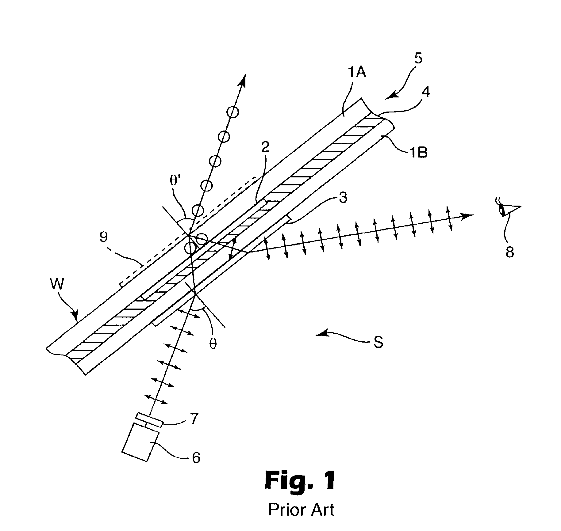
One problem with the system of FIG. 1 is its reliance on reflection at an outer window surface, where water, ice, dirt, and the like can greatly distort or impair the image quality.
Another problem is its reliance on a polarization-direction changing layer: such a layer that works well at large angles of incidence and over the entire visible spectrum is difficult to make, and is not generally available.
Generally, such systems suffer from the fact that some or all of the image light directed toward the viewer is polarized in a horizontal plane, which is the very polarization component rejected by ordinary polarized sunglasses.
Thus if such sunglasses were used, the projected image would become substantially more difficult to see.

Method used


Image

  • Head-up display with polarized light source and wide-angle p-polarization reflective polarizer
  • Head-up display with polarized light source and wide-angle p-polarization reflective polarizer
  • Head-up display with polarized light source and wide-angle p-polarization reflective polarizer

Examples


Embodiment Construction

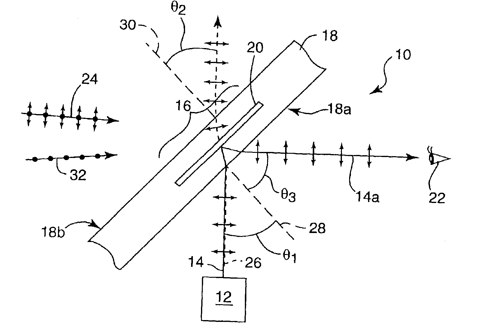
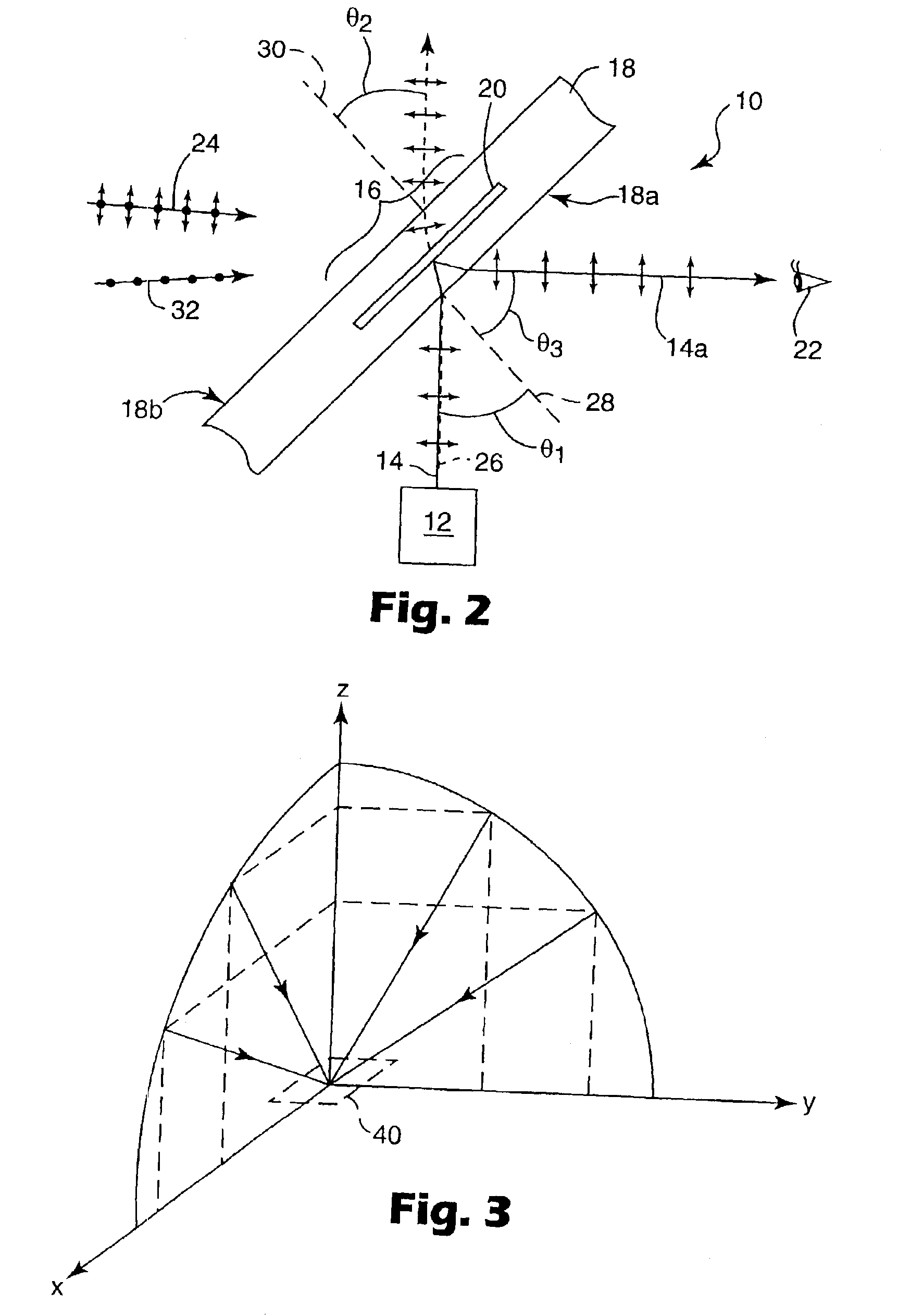
[0027]A partial schematic view of an illustrative HUD system 10 is shown in FIG. 2. In brief, a projection system 12 is provided to direct light 14 towards a target area 16 of a window 18. A reflective polarizer 20, disposed proximate the target area 16, then reflects at least some of the projected light towards the intended viewer 22. Simultaneously, the reflective polarizer 20 and the window 18 transmit at least some light 24 from the outside environment to permit observation thereof by viewer 22.

[0028]Projection system 12 can be a conventional system that projects a visible light beam or image, and can include known elements such as an LCD, electroluminescent panel, incandescent or phosphorescent light source, CRT, LEDs, and lenses, collimators, reflectors, and / or polarizers. The emitted light can be substantially monochromatic, polychromatic, narrow band, or broad band, but preferably overlaps at least a portion of the (visible) spectrum from about 400 to 700 nm. Significantly, ...


PUM

PropertyMeasurementUnit
reflectivityaaaaaaaaaa

Abstract

A head-up display includes a projection system and a window having a target area where a reflective polarizer is positioned to reflect light from the projection system to a viewing area. Light from the projection system is p-polarized and strikes exposed window surface(s) at an acute angle to reduce or eliminate multiple or “ghost” images. The acute angle is closely matched to a Brewster angle of the exposed window surface(s). The reflective polarizer includes a multilayer stack with refractive indices of individual layers chosen to reflect p-polarized light substantially more than s-polarized light over a wide angular range that includes the acute angle. The reflective polarizer also can reflect infrared light to reduce cabin heating from solar radiation.

Description

FIELD OF THE INVENTION[0001]The present invention relates to projection displays that allow a user to see displayed information while keeping vision in the general direction of other sources of information. The displayed information can be reflected from a window, eyepiece component, or portion thereof through which the user can also view the other sources of information.[0002]The term “Head-up display” (HUD) is used herein to refer to such display systems, whether employed in the window of a vehicle such as an aircraft, watercraft, or landcraft (including motor vehicles such as automobiles, trucks, and motorcycles), in smaller scale systems such as goggle lenses or helmet visors, or in other diverse applications.BACKGROUND[0003]A wide variety of HUD systems are known. Commonly, a projection system is combined with a partial mirror (a partial reflector and partial window) as the final optical component for forming a projected image viewable by the user. Simultaneously, the user can ...

Claims


Application Information

Patent Timeline
Patent Type & Authority Patents(United States)
IPC IPC(8): G02B27/01G02B27/00G02B5/30
CPCG02B5/305G02B27/0101G02B2027/012B32B17/10036B32B17/10458B32B17/10761G02B5/30G02B27/01
Inventor WEBER, MICHAEL F.OUDERKIRK, ANDREW J.WHEATLEY, JOHN A.BRODD, JONATHAN
Owner 3M INNOVATIVE PROPERTIES CO
Learn More